The information in this section explains the various factors used in calculating design loads and in resisting those loads to ensure roofs are structurally sound and meet the objectives of NZBC B1 Structure.
The designer must be familiar with the performance requirements of the New Zealand Building Code (NZBC). Loads can be calculated by following the relevant standard, while maximum span and fastening patterns can be specified following the manufacturer's literature.
For buildings designed to NZS3604:
G550 Steel Cladding Fastening Pattern Tables, and
Aluminium Fastening Pattern Tables
For SED projects to AS/NZS 1170, designers can use:
Steel Cladding Wind Load Span Graphs, and
Aluminium Cladding Wind Load Span Graphs.
It is the responsibility of the roofing contractor to install roof cladding according to the design and raise any concerns with the designer before commencement.
B1.2 Building elements shall withstand the combination of loads that they are likely to be subjected to through construction or alteration, and throughout their lives.
B1.3.1 Building elements shall have a low probability of rupturing, becoming unstable, losing equilibrium or collapsing during construction or alteration, and throughout their lives.
B1.3.2 Building elements shall have a low probability of causing loss of amenity through undue deformation, vibratory response, degradation, or other physical characteristics throughout their lives.
B1.3.3 Account shall be taken of all physical conditions likely to affect the stability of building elements including:
Self-weight.
Imposed gravity loads arising from use.
Temperature.
Earth pressure.
Water and other liquids.
Snow.
Wind.
Fire impact.
Differential movement.
Influence of equipment services and non-structural elements.
Time dependant effects including creep and shrinkage.
B1.3.4 Due allowance shall be made for
the consequences of failure,
the intended use of the building,
effects of construction activities,
variation in the properties of materials, and
accuracy limitations inherent in the methods used to predict the stability of building elements
Roof and wall cladding must structurally comply with the performance requirements of NZBC Clause B1 Structure. Loads are derived from AS/NZS 1170, and those loads have been used to develop prescriptive solutions such as found in NZS 3604, NASH, and the Code of Practice load/span tables.
Designers should be familiar with the current Loadings Code, including amendments. Manufacturers' printed technical literature should comply with the current requirements of ASA/NZS 1170.
The Loadings Code identifies four load categories relevant to metal roof and wall cladding.
Wind actions:
Wind imposed inwards forces (pressure) where the wind is slowed, and outward pressures (suction) where the wind accelerates. The shape of the structure induces local pressure factors where pressure is concentrated. Internal pressures may also be generated within a building.
Permanent action: Dead load is the permanent weight of the roof structure and the permanent part of an imposed load, such as an air conditioning unit.
Imposed action: Live loads are variable loads imposed on the building by its occupants and contents, such as a person standing on the roof (point load).
Induced actions: Loads such as wind, snow or ice, and ponding rainwater.
When a structure, or part of it, fails to fulfil its expected basic functions, it is said to have reached a limit state; the two limit states are Serviceability Failure and Ultimate Failure. (see 3.7 Modes of Failure.)
NZS 3604 Timber Framed Buildings is an acceptable solution to comply with the NZBC for light timber frame buildings not requiring specific design.
It contains prescriptive dimensions for purlin spacing and fasteners, based on maximum design wind speeds of Low (32 m/s), Medium (37 m/s), High (44 m/s), Very High (50 m/s), or Extra High (55 m/s). The load calculations for NZS3604 were based on a simplified interpretation of AS/NZS 1170. These values can be used for calculation of loads on the cladding of structures designed using NZS 3604.
NZS 3604 includes:
Timber frame construction.
Height from lowest ground to the highest point on the roof may not exceed 10 m.
A snow load may not exceed 1.0 kPa, although Section 15 of NZS 3604 does provide additional criteria for 1.5 kPa and 2.0 kPa snow loads.
NZS 3604 excludes:
buildings dedicated to the preservation of human life;
buildings which may host crowds;
publicly owned buildings containing high value contents; and
curved roof construction.
Because the buildings covered by this standard are limited in size, wind loads include a local pressure factor of 1.5 kPa over the entire structure, rather than varying factors according to the position on the roof as required by AS/NZS 1170.2:2011.
A structural steel member typically comprises elements named webs and flanges. In a roofing profile the sides of the rib act as a web, and the pan and crest act as flanges.
Steel is strong in tension but can be weak in compression if the profile is not optimised.
Profiled metal cladding acts as a beam, which derives its strength from the ability of its flanges, separated by the web to resist tensile and compressive forces. This strength can only be maintained while those parts in compression are restrained from buckling.
The geometry of the profile shape, together with the material thickness and strength, determines the load capacity of the profile. Manufacturing variations of tested profiles will produce different results in pierced-fastened profiles, under load and may produce vastly different results in clip-fixed profiles.
Profile strength can be determined by analysis of sectional properties, but this will not accurately predict their performance under load, as the profile shape, and therefore the sectional properties, change during deflection. Only physical testing can prove the actual capabilities of the profile.
Profile familes can broadly be segregated as pierce fastened (corrugate, trapezoidal), and secret fix (tray and trough). Within these broad categories there are subsets.
Symmetrical corrugate or trapezoidal profiles have the advantage of being more easily curved around a radius. Because the ribs are necessarily close together, they have the disadvantage of roof traffic loads having to be spread over two crests, and they have a lower run-off capacity.
The corrugated profile has been used in New Zealand for over 150 years and there has been only one significant change during that period.
In the 1960s the steel grade used for roof and wall cladding changed from low-strength steel (250MPa or G250) to high-strength steel (550 MPa or G550). The number of corrugations also changed from 8 to 10.5, which enabled the sheets to be laid either side up, as opposed to over-and-under.
The standard corrugation profile has 17.5 mm deep crests at 76 mm spacings, but smaller and deeper alternatives are also available.
Corrugate cladding is formed with a slightly asymmetrical overlap profile to a capillary barrier.
The trapezoidal shape provides greater water carrying capacity and provides greater spanning capabilities than corrugate profile.
The angle and height of the trapezoid rib determines the profiles performance under compression. A deeper rib generally gives improved performance, but lowers the effective coverage of the sheet.
Various miniature cladding profiles are manufactured in New Zealand, the most common being known variously under the names of mini-corrugate, sparrow iron, baby iron and mini-iron.
Mini-corrugate is sometimes used for small roof areas, such as spires and awnings. It is most commonly used for wall cladding, parapets and internal linings where studs are normally spaced at 600 mm centres or less.
Some miniature trapezoidal profiles are also manufactured specifically for wall cladding.
Secret fixed profiles are attached to the structure by clips rather than by pierce fasteners. This allows for freer thermal movement and minimises the number of penetrations in the cladding. The steep sided ribs and wide pans typical of secret fixed profiles gives greater water carrying capacity, and facilitates watertight flashing design.
Traditionally they were used for pitches as low as 1° but due to durability issues caused by deflection and resultant ponding the recommended minimum pitch is now 3°.
Trough sections generally have 2 to 3 pans or trays 180 – 250 mm in width. Tray roofing has a single pan of up to 550 mm in width.
Standing Seam is a subset of tray roofing. Standing seam roofs are based on traditional manufacturing methods (using folding and hand tool rather than roll forming), but now they are available roll-formed in most itirations. (See 15.4 Tray Roofing)
To test for tensile strength the material is subjected to a longitudinal (stretching) load, and values are taken for yield strength (when it permanently deforms) and tensile strength (when it breaks). Elongation is also measured during this test.
The minimum tensile strength defines the grade of steel, eg, G550 for high-strength light gauge steel, but to comply with this grade the yield strength and elongation must also fall within defined parameters.
Yield strength is an important determinant of the strength of a profile, along with profile shape and material thickness. High tensile material will have more resistance to failure such as buckling around the fastener under wind uplift, pull-through of the fastener head, or buckling under foot traffic load. However, tensile strength has a negligible effect on deflection under load.
Where 0.55 material is specified for straight corrugate or trapezoidal roofing, it is unacceptable to substitute G300 for G550 grade material as the resultant profile will have little strength advantage over 0.40 mm G550.
Aluminium is defined by a hardness grade ranging from H32 to H38. Typically, H34 is used for flashings, severe profiles such as trough sections, and profiles that are to be curved. Most corrugated and Trapezoidal profiles are manufactured using H36.
It must be remembered that the alloy also affects strength. H36 aluminium in 5005 or 5025 alloys, which are typically used in New Zealand, will have considerably greater tensile strength than the same grade in a 3000-series alloy.
Material thickness has a great bearing on load capacity and buckling resistance. For residential buildings, 0.40 mm thickness material is most commonly used for corrugated and trapezoidal profiles, and this will normally be sufficient to withstand the statutory wind loads at typical spans and fastener spacings in up to High Wind Zones. In higher wind speeds, it is often more effective to use 0.55 mm material, rather than reducing purlin and fastener spacings.
Material with a 0.40 mm thickness is very vulnerable to foot traffic damage in most profile configurations and requires careful and accurate foot placement to avoid buckling. In residential buildings with high foot traffic expectancy or highly visible roofs, eg, multi-level mono-pitch roofs, roofs with UV collectors, flues, aircon devices, chimneys that need servicing, or prestige housing 0.55 mm material should be selected.
For commercial and industrial applications, 0.55 mm is almost universally used on the roof, and 0.40 mm is most common on walls.
In addition to 0.40 mm and 0.55 mm, 0.48 mm G550 steel is often used for high tensile trough sections, which will often compare in strength to similar profiles manufactured from 0.55 mm G300 material. Most roofing profiles can also be manufactured from 0.75 mm G550 material where greater robustness and resistance to foot traffic are desired.
Material is available with other thicknesses; for example, 0.63 mm material is often manufactured for the Pacific islands, and 0.35 mm is sometimes used to manufacture specialist wall cladding.
The performance and optimal use of metal cladding is affected by the different types of load it is subjected to during the course of its lifetime. These loads can be broadly categorised as point load and uniformly distributed load (UDL).
Modes of failure and fastener loads are discussed in other clauses under the main clause 3 Structure.
The performance of profiled metal cladding under load depends on its ability to resist the tension (stretching), compression (squashing), and shear (sliding) forces that it is likely to be subjected to during the lifetime of the building.
When a beam is subjected to bending, one flange will be under compression and the other under tension.
Loads acting on roof cladding are generally classified into two types: point load and uniformly distributed load (UDL). A point load is applied to a particular area, but a UDL impacts on the total area of the roof.
Optimum performance of roof cladding under load depends on the continuity over several spans.
An adjacent continuous span assists the performance of profiled metal cladding, as continuity can reduce deflection up to 50%. In single spans the cladding is free to rotate at each support, but with continuity at a support the cladding is held down by an adjacent span; reducing the rotation and deflection.
Load distribution greatly affects the deflection. A load distributed equally along the length of a beam (line load) will cause less deflection than the same load being applied to the centre of the beam.
The depth of the profile of metal cladding is another important criterion in the design and use of metal roof and wall cladding. Given the same cross section area, the deflection of the profile will vary with the square of the depth, with the trade-off of higher buckling modes.
Most roofing profiles will resist far greater point loads when the load is applied to the pan of the profile rather than the rib. When the load is applied to the pan, the load is shared by the adjacent ribs. Alternatively, loads may be applied over two or more ribs.
Testing loads may be applied to the pan or the rib depending of the profile shape and the design criteria. See 3.7.4 Roof Traffic.
Trafficable roofs must be designed to withstand a point load which is representative of a worker with a bag of tools. It is calculated at 112 kg, which equals 1.1 kN force.
In the case of an imposed load, such as an air conditioning unit which is supported directly by the roof cladding, the unit weight per support and area of contact is calculated to arrive at point loads.
A point load on a roof is always positive or downward (+).
3.6.2 Uniformly Distributed Load (Wind or Induced Action)
A Uniformly Distributed Load (UDL) is commonly either a wind load or a snow load. These loads are variable and depend on factors such as the location, topography, and position on the structure, but do not often exceed 6 kPa. The most severe wind load is usually an uplift load, or negative (-), and snow load is a downward load or positive (+).
The wind load imposed on a roof structure is taken to apply at right angles to the roof cladding over a nominated area. The design wind load is affected by the design of the building and is modified using factors called pressure coefficients. Wind design load is measured in kilopascal (kPa); 1 kPa equals 1 kN/m².
Under wind loads, inwards loads are resisted by the purlin or girts, whilst outward loads are only resisted by the fastener head or clip. Therefore, outwards load is the more critical figure.
Engineers calculate both the serviceability load and the ultimate load. They compare these values with the maximum failure loads of the products and systems they are considering.
Load/span data for standard corrugate, and low rib 5 and 6 ribbed trapezoidals is at the end of this section.
Refer to manufacturer's load/span tables for all other profiles, which should give the maximum recommended load for continuous spans when tested as described in 17.1.3 Testing Procedure.
Terrain also has a big effect. Structures near the crest of a rise or on flat land near a steep face will have increased design wind pressure.
Wind Design Load is affected by building design factors such as building height, shape, proportions, orientation, and roof pitch. Permeability can also be a big factor; buildings with large openings on one side but completely closed on the other three sides will suffer high internal wind pressures. These internal pressures must be added to the suction load on the outside of the roof when calculating wind design load.
Local territorial authorities are usually able to give wind speed figures for a specific address in their area. All other factors, including topographical influences, internal, and local pressure factors must be considered by a suitably qualified professional to calculate the design wind load on a structure.
The local pressure factor (Kl) is an important design consideration required by the Loadings Standard. The peripheral areas of roof and wall surfaces are subjected to greater uplift loads than the main body of the roof. Designers need to include local pressure factors in the calculation of wind loads on the cladding.
When determining fixing requirements to NZS 1170.2, the engineer should prepare a roof map showing purlin spans and local pressure factors for each section of the cladding.
When designing to NZS 1170 the local pressure factors are:
1.5—applied to the edges of all buildings at a dimension equal to 0.2 or 20% of the width or height of the building whichever is the least.
2.0—applied to the edges of all buildings at a dimension equal to 0.1 or 10% of the width or height whichever is the least.
3.0—applied to roof pitches less than 10°, at the corners where the dimensions in (a) intersect. It also applies to corners of walls where the building height is greater than the building width.
The basic formula for converting a wind speed to wind load is: 0.6 x velocity²= wind load. However, to get a true design wind speed is a lot more complex; various factors have to be applied including roof self-weight, internal pressure and local pressure coefficients.
The most influential of these factors is generally the local pressure factor, but internal pressure can also have a profound influence—particularly on unlined structures.
Roof cladding design does not usually have to be altered for snow load, maximum snow load in New Zealand (under NZS 3604) is a UDL of 2 kPa.This is less than the upwards load in a Very High Wind Zone, however, as it is a downwards load, restraint is linear by the purlins, rather than point restraint by the fasteners, so greater capacity is achieved.
Any profile-gauge combination that will resist a wind load of Very High or Extra High Wind Zone with fasteners at each crest, will adequately resist a 2 kPa snow load. It may, however, be neccessary to increase the strength of the structure to allow for induced snow loads.
NZS 3604 divides New Zealand into six zones where the maximum snow load is 2 kPa; areas above specific altitudes in these areas require specific design.
Projections such as gutters, flashings and chimneys need additional fixings and detailing to resist loads from sliding snow. It is normal to fit snow straps to residential gutters in snow prone areas.
The self-weight of light-weight profiled sheet cladding should be included in the calculation of net wind load, but is a minor factor and, typically, works in the opposite direction to wind loads.
Initial failure under wind uplift for pierce-fastened cladding is usually by local buckling of the rib crest adjacent to the fastener. While the cladding can still resist a load, this permanent deformation is liable to cause leakage at that point; therefore, it is a serviceability failure and is often the limit state for trapezoidal profiles. Medium and high rib trapezoidals may have ultimate loads as the determining factor.
Failure under wind load for clip-fastened cladding is usually by the clips de-indexing and the cladding sheets blowing off. This is an ultimate failure.
If a standard corrugate or low rib trapezoidal product passes UDL for serviceability it will comfortably exceed ultimate design load requirements. For medium and high ribbed trapezoidal, both serviceability and strength loads should be checked. Clip-fastened products are typically restricted by strength load only.
Point load resistance should also be checked against the expected roof traffic load of the finished structure. (See 3.7.4 Roof Traffic)
Deflection is the temporary bending of roof or wall cladding that occurs under load when the material is subjected to forces within its elastic limits.
Deflection under distributed load is a voluntary limit of wall cladding, deformation causing residual deflection after application of point load is a serviceability failure of roofing.
Temporary deflection under load is not considered for roof load tables as it has not been found to affect weathertightness. Temporary deflection under load of wall cladding is a recommended limitation for aesthetic reasons, but it is not mandatory.
Deformation is a permanent alteration to the profile's shape that occurs when the material is taken beyond its elastic limits. This is most often seen as deformation under the fastener head after high outwards loads, or buckling of the rib after the imposition of a point load
With high-strength claddings buckling failure is often quite sudden and severe once the point of yield is reached, while progressive deflection under repeated loads within the material’s elastic limit is minimal.
Low-strength (G300) steel or non-ferrous metals can progressively yield under repeated heavy foot traffic, and are more prone to point load damage. This should be considered at the design stage. Machine roll-curved, crimp-curved cladding, and metal roof tiles are usually made from low-strength steels.
It is not acceptable for G300 steel to be substituted for G550 steel in products that are traditionally run from high-tensile strength material.
The designer must consider the degree and type of foot traffic that may be expected on a roof. The following requirements are subjective standards and must be considered in line with customer expectations, and building use and type.
More robust design than specified below (reducing purlin spacing or adding protection from mechanical action), is required for roofs that are regularly accessed, roofs used as staging by subsequent trades, or areas that are adjacent to access points, particularly step down access.
Type A – Unrestricted Access
Type A are roofs:
that need to be regularly traversed by the roofer for access during installation;
that will be accessed regularly by sub-trades;
that butt on to walls or windows that may require maintenance;
that have plant, chimneys, or solar installations requiring regular maintenance; or
that require regular access for clearing gutters or spouting of debris.
For Type A roofs, the cladding must resist the load of 1.1 kN applied to the pan or a single rib, and a strength load of 2 kPa applied to the weakest point.
Type B – Restricted Access
Type B are roofs:
that are simple in design and do not have to be regularly traversed by the installer;
which are infrequently accessed by qualified trades people for maintenance; or
with a pitch of more than 35°.
For Type B, roofs the cladding must resist the load of 1.1 kN applied to the pan or over two ribs and a 2 kPa load applied to the weakest point.
Type C – Non-Trafficable
Type C are roofs:
where supports are required to be laid to support roof traffic, or traffic should take place within 300 mm of purlin lines,
which have a pitch of 60° or greater; and
including non-trafficable translucent roof sheeting.
For Type C roofs, the cladding must resist the minimum load of 0.5 kN applied to the pan or over two ribs.
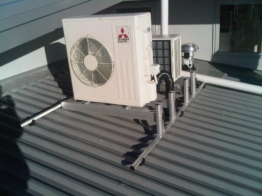
Any permanent load added to the roof cladding or structure is termed imposed; that includes air-conditioning equipment, solar installations, television aerials, anchor points, and walkways.
All loads must be supported on the rib of the profile or through the profile to the primary structure. Any attachment to the roof cladding must be compatible with the cladding, or isolated from it.
An air conditioning unit correctly installed on a roof, using durable and compatible materials.
No additional equipment must be directly connected to the cladding without considering the effect of increased dead and live loads.
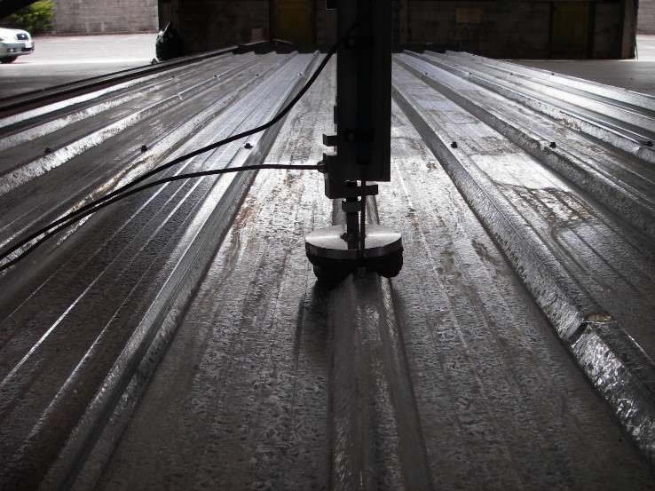
When designing installations for placement on the roof, the roof traffic implications of installing and servicing such must be considered when determining point load resistance requirements.
Construction loads on a building include the wind load on a partially clad or braced roof or building. Depending on the method and sequence of construction, it can be greater than the load on a completed building. Construction loads also include temporary localised loads from material storage, scaffolding, and tradespeople.
Other forces contributing to construction load include:
The intensity of internal wind pressures due to a temporary absence of ceilings, walls and glazing.
Storage of roof cladding on the structure. Bundles of roof cladding should be placed so they do not cause overstress in purlins.
Any scaffolding above an existing roof must be designed to avoid damage to the roof structure or coatings, and be designed or sequenced to avoid wet storage corrosion. It is far better practice to stage jobs so that lower roofs are not used as a working platform for work on higher levels
All metals may be subjected to fatigue under repeated heavy load conditions.
While high-strength steel is susceptible to fatigue, this seldom happens in practice. Aluminium brackets and clips have been known to fail by fatigue and this should be considered in designing such items.
Other metals, such as lead and copper, are restricted in length or overall panel size to avoid cracking by fatigue. Sharply folded corners should be avoided on these materials and the minimum radii requirements should be followed.
Hydrogen embrittlement can occur when folded items such as external gutter brackets are subjected to post-forming hot dip galvanizing. This can be avoided by forming to radii appropriate to the material grade and thickness being formed.
Most fastener failures happen due to negative load (or uplift) resulting in pull out of the screw from the support, or the screw pulling through the cladding or causing permanent deformation. Testing procedures are designed to closely simulate these conditions.
Product testing does not include pull-out of the screw, this should be checked independently.
Fastener failure by fatigue can occur when fasteners embedded in timber or hot rolled steel, are subject to frequent bending action by repeated thermal expansion forces. This is unlikely to happen to cold rolled steel purlins up to 2.5 mm in thickness as the thinner depth of connection of the screw into the purlin allows it to rotate, rather than bend.
A fastener penetration of three threads through the steel member is sufficient for the fastener to meet its full design capacity. Pull-out failure of screws must be checked when assessing a profile's load/span capacity.
The pull-out values of screws into light gauge steel battens or purlins varies greatly with thread design, pitch, and drill point shape. When fastening into light gauge steel, the pull-out values of the specified screw must be considered, and the installation must be completed with that type, gauge, and brand of screw. In light gauge steel under 1mm in thickness, it is also important to avoid stripping out the formed screw thread
Timber purlins generally require a fastener penetration of 30 mm. With this level of embedment, a screw equipped with a profiled washer though 0.55 material will fail by pull-through of the cladding before it fails by fastener withdrawal from the timber. Greater thicknesses of cladding may require specific design. For fastening into sarking or rigid air barrier less than 30 mm thick, the pull-out values for the specific screw and sarking material should be obtained from the supplier and required fastener pattern calculated.
Pull-over values for medium and high rib trapezoidal profiles must be checked against strength loads provided by testing.
Pull-over load depends on the head or washer size. For example, as 12# and 14# screw heads have approximately the same diameter, these screw sizes have the same design load value for pull-over. If the pullover load is likely to be exceeded, the options are to increase the metal thickness or use a load-spreading washer.
Profiled load-spreading washers spread high wind uplift-loads over a larger area around the fastener head. Using load spreading washers under the fastener can increase the load resistance of each fastener by up to 50%.
The type, size and stiffness of washers are critical for performance. Where performance data incorporating load-spreading washers is used, the specification of the washer must be quoted with the fastener.
In general, load-spreading washers should have a minimum thickness of 0.95 mm for steel and 1.2 mm for non-ferrous metal.
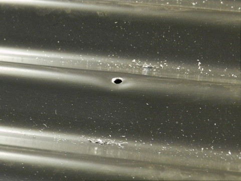
Where oversized holes are used to accommodate thermal movement of the sheeting, load-spreading washers should be used with sealing washers to ensure weather tightness.
The maximum overhang for all corrugate and low trapezoidal profiles is 150 mm, unless a product has been specifically tested to withstand point load and design wind loads at a greater overhang.
The allowable overhang distance of various cladding profiles will depend on their section properties.
When using trapezoidal profiles, greater overhangs can be achieved by stiffening the edge of the sheet in various ways; the most common being using a square gutter with a horizontal flange, but this should be fastened on every pan to achieve continuity.
The limit placed on low trapezoidal profiles with a stiffened overhang is 300 mm but it is not suitable for corrugate.
The overhang distance can be increased for some trapezoidal profiles with a rib height greater than 28 mm, but this distance must be proved by testing.
Where the cladding is fixed at a ridge or apron, the overhang distance can be increased to 250 mm from the end of the sheet, as the cladding is not subjected to the same point load or UDL and the load is shared with the flashing.
Point of access and expected roof traffic loads must also be considered.
These fastening patterns should be used in conjunction with load span graphs.
The load on a purlin and a purlin/rafter connection is determined by the wind load and the area of roof the load is acting upon. Roof fasteners transfer wind uplift-loads to the purlins, which in turn transfer them to the primary structure.
Fastening to every second purlin may be within the roof's load/span range, but will double the load acting on the fastened purlins. All purlins must be fastened to unless alternate purlins are specifically designed to take the additional loads
3.10 Fastening Pattern Tables – Designs to NZS 3604
Fastening Pattern Tables should be read in conjunction with the constraint of access and the span at which the point load will be the limiting factor.
The performance of profiled metal cladding depends on the profile shape, thickness of the metal, the span, and the fastening type and pattern. These values can be greatly enhanced by using load-spreading washers or thicker material.
3.10.2 Maximum Spans and Fastening Patterns for Corrugate Wall Cladding
The maximum span for pan-fastened wall cladding is generally governed by temporary deflection under load, rather than permanent deflection around the fastener.
"The Metal Roofing and Wall Cladding Code of Practice (COP) can be used to support designs for vertical corrugate cladding at spans greater than 480 mm. These spans are less than what is quoted for roofing, because in the case of wall cladding we have limited loads to a deflection limit as described in the attached table."
The deflection criteria used in this table is span/120 + P/30, where P = the space between fasteners. Higher deflection limits may be acceptable in certain circumstances.
3.11 Wind Load/Span Graphs – Designs to AS/NZS1170
Wind load/span graphs allow designers to ascertain spanning ability and fastener spacing requirements for designs outside of NZS 3604. They should be read in conjunction with the point load limitations appropriate to the degree of traffic predicted on the roof.
NZMRM wind uplift resistance testing specifically assumes fasteners are permanently fixed to the purlins and will not pull out. Because of this and, also due to the huge range of fastener/purlin material variations, the pull-out resistance of fasteners is eliminated from the uplift testing procedure. Accordingly, when designing for SED wind conditions, the engineer must make a separate calculation to determine the necessary pull-out resistance of the fastener from the purlin material to be used, which will allow the correct selection of the fasteners.
The performance of profiled metal cladding depends on the profile shape, thickness of the metal, the span, and the fastening type and pattern. These values can be greatly enhanced by using load spreading washers or thicker material.
All the tests from which these graphs have been derived used the 2:3 ratio of end to intermediate span and the graphs shown are for intermediate spans only. End spans must be reduced by two-thirds for these values to be assumed.