Access the Code of Practice online

This registration will be required once-only per browser/device, which is achieved using a cookie stored on your device.

There is no password required, and your information will not be shared with any third parties.

Please register and accept the terms for the NZMRM online COP
By ticking this box you confirm that you have read and accept the Terms listed below


Disclaimer

Although the information contained in this Code has been obtained from sources believed to be reliable, New Zealand Metal Roofing Manufacturers Inc. makes no warranties or representations of any kind (express or implied) regarding the accuracy, adequacy, currency or completeness of the information, or that it is suitable for the intended use.

Compliance with this Code does not guarantee immunity from breach of any statutory requirements, the New Zealand Building Code or relevant Standards. The final responsibility for the correct design and specification rests with the designer and for its satisfactory execution with the contractor.

While most data have been compiled from case histories, trade experience and testing, small changes in the environment can produce marked differences in performance. The decision to use a particular material, and in what manner, is made at your own risk. The use of a particular material and method may, therefore, need to be modified to its intended end use and environment.

New Zealand Metal Roofing Manufacturers Inc., its directors, officers or employees shall not be responsible for any direct, indirect or special loss or damage arising from, as a consequence of, use of or reliance upon any information contained in this Code.

New Zealand Metal Roofing Manufacturers Inc. expressly disclaims any liability which is based on or arises out of the information or any errors, omissions or misstatements.

If reprinted, reproduced or used in any form, the New Zealand Metal Roofing Manufacturers Inc. (NZMRM) should be acknowledged as the source of information.

You should always refer to the current online Code of Practicefor the most recent updates on information contained in this Code.

Scope

This Code of Practice provides requirements, information and guidelines, to the Building Consent Authorities, the Building Certifier, Specifier, Designer, Licensed Building Practitioner, Trade Trainee, Installer and the end user on the design, installation, performance, and transportation of all metal roof and wall cladding used in New Zealand.

The calculations and the details contained in this Code of Practice provide a means of complying with the performance provisions of the NZBC and the requirements of the Health and Safety at Work Act 2015.

The scope of this document includes all buildings covered by NZS 3604, AS/NZS 1170 and those designed and built under specific engineering design.

It has been written and compiled from proven performance and cites a standard of acceptable practice agreed between manufacturers and roofing contractors.

The drawings and requirements contained in this Code illustrate acceptable trade practice, but recommended or better trade practice is also quoted as being a preferred alternative.

Because the environment and wind categories vary throughout New Zealand, acceptable trade practice must be altered accordingly; in severe environments and high wind design load categories, the requirements of the NZBC will only be met by using specific detailing as described in this Code.

The purpose of this Code of Practice is to present both Acceptable Trade Practice and Recommended Trade Practice, in a user-friendly format to ensure that the roof and wall cladding, flashings, drainage accessories, and fastenings will:

  • comply with the requirements of B1, B2, E1 E2 and E3 of the NZBC;
  • comply with the design loading requirements of AS/NZS 1170 and NZS 3604 and with AS/NZS 1562;
  • have and optimised lifespan; and
  • be weathertight.

COP v24.03:Internal-Moisture;

10 Internal Moisture 

The science of internal moisture control is concerned with the need to manage and control condensation, mould growth, and corrosion.  
The outdoor environment, the building design, and occupant behaviour affect humidity in the living spaces, which ultimately affects humidity in the ceiling space.  
This section of the COP focusses predominantly on managing humidity in the ceiling space of dwellings. Shorter sections also cover the design of non-residential roof and wall cladding, which may also be affected by excessive internal moisture. 


10.1 NZBC Clause E3: Internal Moisture (Extract) 

Source: Acceptable Solutions and Verifications for New Zealand Building Clause E3 Internal moisture.​

10.1.1 E3 Objective 

Safeguard people against illness, injury, or loss of amenity that could result from the accumulation of internal moisture.

10.1.2 E3 Functional Requirements 

Buildings must be constructed in a way to avoid the likelihood of:

  • fungal growth on linings and other building elements, and
  • damage to building elements due to the presence of moisture.

10.1.3 E3 Performance Requirements 

NZBC Clause E3 requires building practices to ensure an adequate combination of thermal resistance, ventilation, and space temperature in all habitable spaces, bathrooms, laundries, and other spaces where moisture may be generated or accumulate.

10.1.4 Compliance 

New Zealand Building Code clauses E3 – Internal Moisture and G4 – Ventilation focus on air quality and accumulation of moisture in occupied spaces. The acceptable solutions for these clauses do not specifically require ventilation of attic spaces.

While problems with excessive internal moisture in attic spaces are relatively uncommon, they can be severe. A poorly designed ceiling cavity, even above a well-aired room, can give rise to internal moisture problems in the attic space, which can affect the air quality of the occupied space below and may cause health and durability issues.

The COP requires building techniques which encourage trickle ventilation of all spaces in buildings; and requires specific ventilation design for:

  • flat roofs,
  • sarked roofs,
  • skillion roofs,
  • barrel curved and prickle-ridged roofs, and
  • roofs with ceilings which allow easy passage of moisture vapour.

Long (over 12 m spans), shallow-pitched (less than 12°) roofs should also be designed to allow natural ventilation.

Generally, there is no need to make provision for moisture control in industrial and most commercial buildings due to them being either well-ventilated or climate-controlled. In buildings with valuable or delicate stock, the possibility of dripping condensation needs to be assessed.

Roofs in cold areas where numbers of people may come in wet at the end of the day, such as ski lodges and tramping huts, require specific design.

Buildings designed to accommodate large numbers of people (such as theatres, sports areas and educational buildings) and areas creating particularly high moisture levels (e.g. swimming pools) should have ventilation solutions designed by a specialist engineer.

10.2 Why Manage Internal Moisture 

Internal air quality is a major cause of respiratory illness, which has been reported as costing the country $6 billion per annum, with respiratory-related illnesses accounting for one in ten of overnight hospital admissions.

Dust mites grow up to ten times faster in damp environments and contribute to allergic reactions and asthma.

The most recent BRANZ Home Condition Survey identified mould ranging from moderate to severe in 22% of New Zealand houses. Mould was worst in rental accommodation, where much of our most vulnerable population live.

In addition to the health effects, excessive internal moisture impacts material durability. In the roof space, this can affect the roof cladding, underlay, purlins, trusses, fasteners, and seriously affect the durability and structural integrity of those components without being apparent to the occupants.


10.3 Special Requirements 

Buildings of the following types using metal cladding should have a sealed vapour barrier and are outside the scope of this Code of Practice. They require specific design.

  • Swimming pools.
  • Buildings containing liquids stored in open containers.
  • Buildings where water is used in manufacturing, cleaning or storage processes.
  • Ice rinks, cold stores and freezers.
  • Buildings where unvented gas heating is used.


10.4 Condensation 

Condensation is a natural phenomenon and building materials are capable of withstanding repeated short-term episodes of wetness. Problems arise in ceiling spaces when more water vapour enters than exits, and materials stay wet for long periods, or where standing water accumulates.

The primary purpose of roof cladding is to act as a rain screen so that no water enters the building from the outside. It is, however, equally important to ensure that the building is kept dry from inside. Because metal is a good heat conductor and is not absorbent, condensation forms on metal cladding under conditions of high humidity when surface temperatures drop below the dew point.

The solutions in the Code of Practice apply to cold roofs, where there is a gap between the ceiling insulation and the roofing material. 10.12.2 Warm Roofs require specific design to avoid internal moisture problems. They are discussed in more detail under 15.5 Warm Roofs.

10.5 Building Airtightness 


Changing building techniques and materials — eg, impervious cladding and linings, and aluminium joinery — have led to buildings becoming progressively more airtight. Many of these changes have been led by the desire to increase energy efficiency. Other building changes include unsealed downlights, which can allow ready entry of water vapour into the ceiling space, and the demise of the open fireplace which provided considerable ventilation to the living areas of a home.

Occupant behaviour has also changed. More families shower daily and then leave the house unoccupied and closed-up for much of the day and night. Less activity means a low level of air changes per hour.

These changes can lead to internal moisture problems. As water vapour is lighter than other atmospheric gases, much of the moisture tends to migrate upwards into the ceiling cavity.


10.6 Insulation 

The increase in ceiling insulation standards helps prevent heat leakage into the ceiling space, but it does not affect the passage of water vapour. Ceiling insulation excludes more heat from the ceiling cavity, resulting in colder cavity air temperatures. Warmer air can hold more water vapour than cold air. Therefore, colder temperatures in the ceiling cavity lead to an increased risk of condensation.

10.6.1 Insulation Position 

Insulation must be positioned so that there is a gap of at least 20 mm between insulation and roofing. On flat ceilings, or buildings without eaves, it must be placed so the gap is maintained at the eaves or an eaves insulation barrier should be fitted. To achieve this, an eaves insulation barrier may be required.

10.6.2 Other Insulation 

Reflective foils are not defined as insulating, because they are only somewhat effective against radiative heat loss and have little impact on conductive and convective mechanisms. They also increase the potential for electrocution. As they are non-absorbent, they are not permitted as residential roofing underlay in New Zealand.

When Polyester blanket insulation is used in conjunction with metal roof cladding, special roofing screws should be used to avoid binding.

Composite insulated metal panels are described in 15.5 Warm Roofs.

Insulation must not be laid over the purlins as this compromises the air gap and the efficiency of the insulation where the roofing compresses it.


10.7 Climate 

Being narrow, mountainous, islands lying in the path of strong prevailing winds, New Zealand is subject to high rainfall and high humidity. Compared to much of the world — where 70% relative humidity is considered the threshold of corrosion and health problems — New Zealand has very high humidity, particularly in northern regions, where the mean annual humidity levels are often around 80% or more. This means the dew point (temperature at which condensation begins to form) is also higher than in colder but drier climates.

The design requirements to deal with this environment are specific to New Zealand, which is reflected in our building practices. It is not advisable to use design or installation practices from countries with different environmental conditions without a comprehensive assessment of the management of internal moisture under NZ conditions.

10.7.1 Humidity 

Relative humidity (RH, given in per cent [%]), is the most widely known method: It gives the content of water vapour in the air relative to the maximum amount of water this parcel of air can hold at its present temperature.

Other measures are absolute humidity and water vapour pressure.

10.8 Moisture Sources 

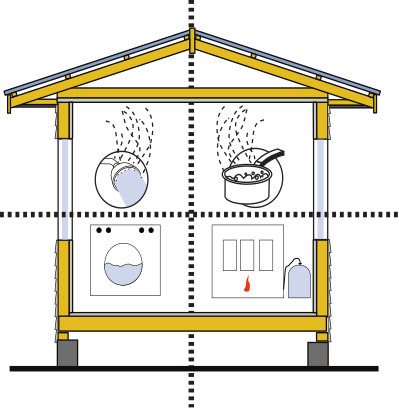
Everyday household activities, heating, indoor plants, pets and construction activities all contribute to indoor moisture.


10.8.1 Occupant Behaviour 

The occupants of the building create a significant amount of water vapour. Therefore, the air inside in a building typically has a higher moisture content than the external atmosphere.

10.8.1B Approximate Amount of Water Vapour from Occupant Behaviour

Occupant behaviourEstimated Amount of Water Released (per 2.5 inhabitants)
Cooking (unventilated)3.0 L / day.
Baths / Showers1.5 L/day. 
Clothes Washing0.5 L/ day.
Clothes drying (unvented)5.0 L/ load.
Dishwashing1.0 L / day.
Portable gas heaterup to 1.6 litres per 1kg of gas burned.
Breathing  (average)3 litres per day.
Breathing asleep (per hour) (average)50 ml.
Perspiration 0.5 litre per day.
Pot PlantsThe same amount as the input


Bathing and showering, cooking, heating, indoor laundries, and unvented clothes drying are the most obvious sources of water; respiration, perspiration, indoor plants, and pets also produce moisture.

Areas for moisture-generating activities should be well ventilated and the entire building should be mechanically ventilated to outside the structure. Proposed changes to NZBC G4/AS1 will require venting to the outside of appliances such as showers, baths, and cooktops.


10.8.2 Heating 

Some other sources of moisture are best avoided altogether, particularly unvented gas heating and kerosene heaters. Burning 1 kg of gas can release 1.6 litres of moisture into the atmosphere.

10.8.3 Mechanical Venting 

Supply-driven and exhaust-driven mechanical ventilation systems can pressurise or depressurise internal atmospheres in different areas of the building. Supply-driven systems can be problematic as increased internal pressures can drive moist air into the attic through openings in the ceiling.

Exhaust-driven systems can de-pressurise internal areas and increase the intake of moist external air, e.g. ground moisture via a vented cavity. Unbalanced mechanical ventilation can also encourage moisture migration by creating negative pressures in the ceiling cavity. These systems need to be well designed and maintained to avoid the risk of affecting internal moisture. A balanced mechanical ventilation system, where both intake and exhaust are connected to the outside, is the preferred system and will be most effective when the thermal envelope of the building is airtight.


10.8.4 Construction Moisture 

During construction, timber can become wet and take some time to dry out. Some activities, such as plastering and painting, also release water vapour.

Concrete floors are particularly prolific sources of moisture. During curing, a 100 mm thick concrete slab releases approximately 10 litres of water vapour per square metre of surface area. The curing period depends on various factors, but as a rule of thumb, a concrete floor cures at a depth-rate of 25 mm per month. Therefore, a concrete slab can affect internal moisture levels for a considerable period.

All new buildings, particularly those with concrete floors, must be kept well ventilated  (at much higher levels than required during normal use) until moisture levels of construction materials have stabilised.

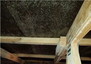
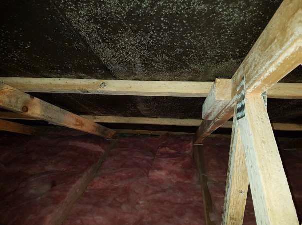
10.8.4A Mould Damage

This building suffered mould damage to underlay and roof truss even before occupants moved in.


10.8.5 Ground Moisture 

Ground moisture can infiltrate living spaces by way of the floor or directly to the ceiling space by way of vented cavities. The cavity should be constructed to prevent the migration of water vapour into the ceiling space. Wet subfloors can be isolated by laying polythene tightly over the surface and taping all joints.  More information can be obtained from the Good Repair Guide: Damp Subfloors (BRANZ).

Concrete floors must be installed over a damp-proof membrane (DPM) to ensure that moisture from within the ground does not penetrate the slab. This membrane can be formed by a polyethene sheet that is taped at the laps and laid over compacted hard fill topped by a sand blinding layer. The DPM must be installed under the full extent of the slab, under any internal or perimeter foundations, extend up to the external edge of the floor slab, and lapped and sealed under the wall damp-proofing system.


10.9 Minimising Ingress of Water Vapour into the Ceiling Cavity 

The first line of defence for managing roof space moisture levels is maintaining low relative humidity in the dwelling areas. The second line is preventing excessive amounts of moisture entering the ceiling cavity. It is recommended that all ceilings are square stopped and all penetrations (cables, pipes, hatches, etc.) are caulked. Only use downlights that are airtight and have a gasket

A gloss painted plasterboard ceiling presents some resistance to the passage of water vapour but is not a complete barrier. Vapour will also find its way through any minor gaps in architectural details, and it is air transport through gaps that is responsible for 95% of the passage of water vapour into the ceiling space.

Ceiling tiles and tongue and groove ceilings are considerably more porous than plasterboard. Unsealed downlights can be a major source of moisture movement into the ceiling cavity and should be avoided where possible.

See BRANZ Facts Roof Ventilation #3 .

In some older New Zealand homes, vapour barriers have been used to limit entry of moist air into the ceiling space, but control of air movement into the cavity and removal of damp air by ventilation is a more practical approach.

Cavity systems prescribed under E2AS1 9.1.8.1, except those behind masonry veneer, are classified as drained not ventilated. That means they must be closed at the top to restrict air movement between the cavity and the roof space. Closing a cavity off at the top still allows reasonable ventilation of the cavity while preventing excessive amounts of moisture rising to the ceiling space.  Alternatively, wall cavities can be vented externally.

10.10 Ventilation Pathways 

Because of the cooking, washing, and respiration of the inhabitants, the humidity in the ceiling cavity is most often greater than that of the surrounding atmosphere.  The space may also be colder than the ambient air at night due to 10.12.3 Night Sky Radiation

Warm air naturally rises but has little tendency to move laterally, except when a strong wind blows into roof vents or causes substantial differences in air pressure on opposite sides of the building. That is why eave-to-ridge ventilation is more effective under typical conditions than side-to-side ventilation.

Ventilation of a cavity space is desired to reduce the accumulation of condensation and assist in removing excess heat. Natural ventilation via the ribs of metal roof and wall cladding can achieve this adequately in normal circumstances, but additional provisions are often necessary. In all cases, air must flow naturally through the profile crests without barriers such as profiled foam filler strips at the eaves and apex, or impingement of bulk insulation.

Many roofs not overtly displaying the signs of excessive moisture build-up would benefit from an increase in ventilation.

Simple techniques to provide a clear path for air to enter, travel along and exit the roof cavity can include:

  • Eaves:
    • Allow air entry by soffit vents, over-fascia or behind-fascia vents, or by using fleece-lined roofing material.
    • Ensuring that insulation does not impinge on the underside of the roof at the eaves. This can be achieved by using a heeled truss or eaves baffle, or both.
  • Body:
    • Ensuring that the air can travel under the roof.  If insulation is flush with the underside of the purlins it can be done using a vented batten between the purlin and the underlay, or by using fleece lined roofing material.
  • Apex:
    • Making the roof underlay discontinuous at the apex by cutting or slitting the underlay and using a vented soft edge or vented ridge.

Sarked roofs must have a gap in the sarking at eaves and apex, or by an alternative eaves-to-apex passage.


With skillion roof or flat roof construction, the air volume is significantly reduced, so moisture saturation levels are more quickly reached. Also with these roof types, air flow paths are more easily obstructed. In skillion roofs with tongue and groove ceilings, a layer of roof underlay immediately above the ceiling will provide a vapour check and air barrier to compensate for the porosity of the ceiling. For more advice on skillion roof ventilation, see https://www.branz.co.nz/pubs/branz-facts/roof-ventilation/4-skillion-roofs/

Roofs continuous over an apex, such as barrel curved roofs or roofs with prickled ridges, must have adequate ventilation to prevent the accumulation of moisture at the apex.

Long low pitched roofs will benefit from increased ventilation which may also assist in minimising thermally induced expansion noise. Ventilation typically increases as the roof pitch increases. Air movement through the crests depends on the spacing and area of the crests, roof pitch, and overall length of the sheeting. Corrugate and trapezoidal roofing provide more ventilation than secret-fix roofing. Ventilation through the crests still depends on air being allowed to enter at the eaves and escape at the apex.

Through or tray section roofs have smaller ventilation channels and may require additional ventilation.

The use of profiled closures at eaves or ridge will create a substantial air barrier and alternative ventilation paths must be created.

Additional roof space ventilation may take the form of:

  • louvre vents in gable-ends,
  • soffit vents,
  • proprietary ridge vents,
  • ventilated soft edge strips on transverse flashings, or
  • mechanical or wind-powered vents positioned close to the apex.

Where eave-vent intakes and ridge-vent exits are both employed, the area of the ridge vents should be less than that of the eave vents. More air escaping at the ridge than entering at the eaves can lower the pressure of the attic cavity and encourage more ingress of moist air from the dwelling area.

In pitches of 30° or less cross venting from eaves to eaves alone is generally enough when combined with natural passive ventilation at the apex.

A common rule of thumb is to have a total ventilation cross-section area equal to 1/300 of the ceiling area. In NZ buildings, much smaller ratios have proven sufficient in most cases.

Increasing roof space ventilation above the insulation has only a small effect on R values. Ventilation of spaces above bulk insulation is not only desirable but prevents insulation losing effectiveness due to absorbing moisture.

Partial filling of a ceiling cavity with bulk insulation in flat roofs can severely reduce the amount of free air available to absorb incoming water vapour, thereby increasing saturation levels. Adding insulation while re-roofing must be done with due consideration; unless the amount of ventilation of the cavity is increased or a vapour check layer is used below the insulation, internal moisture problems can occur.

10.10.1 Methods of Ventilation 

The primary purpose of ventilation is to replace the moist air in the ceiling cavity with drier air from outdoors.

As warm, wet air tends to rise, a vent placed in the soffit or at the lower end of a roof will normally operate as an intake vent and a vent at the apex as an exhaust vent, but wind direction can reverse this relationship. Gable-end vents or vents aligned horizontally will act as an intake or exhaust depending on the wind direction.

10.10.1.1 Soffit Vents 

Soffit vents can be made in a range of styles to suit the application. As wind pressure differentials are highest at the eaves, they are an efficient ventilation solution and they are also very weather resistant. Soffit vents should always be installed to allow free movement of air into the cavity and should not be blocked on the interior side by insulation or other material.


In some applications, vented battens may  be needed to increase airflow

10.10.1.2 Fascia Vents 

Vents above fascia may require re-positioning of the fascia to allow for their depth. Fasica vents should be used in conjunction with a high fronted spouting so that the ends of the sheet and the vent are not exposed to driven rain.

10.10.1.3 Ridge Vents 

Ridge vents, such as continuous or intermittent ridge vents or vented head apron flashings, should always be used in conjunction with intake vents at a lower level.

Saturated water vapour can enter the building when commercial ridge vents are subjected to negative pressures or at times of high humidity associated with mist or fog. Such water vapour can form condensation on the structural framework and appear as a leak. Ridge vents without adequate intake vents can also lead to leakage.


10.10.1.4 Vented Soft Edge 

Typical soft edge is either soft aluminium or perforated aluminium a with PIB rubber backer. The latter is more common.  The PIB rubber, when dressed down on a hot day, can adhere to the roofing surface and prevent the escape of air at the apex.  By removing all or most of the PIB backing this is avoided, and the perforations in the aluminium become an effective pathway for trickle ventilation, while still being an effective baffle against wind-blown moisture.  This product is marketed as vented soft edge and is available from all suppliers.


10.10.1.5 Turbine Vents 

Wind-driven turbine vents rely on wind to rotate the fan blades. This creates a low-pressure area, so they draw air from the ventilated area at a greater rate than stationary vents. The amount of air movement can be dampened but is normally uncontrolled; it is developed as a function of wind speed as well as turbine size and efficiency. Turbine vents, unlike commercial ridge vents, are unaffected by wind direction and they are less prone to leaking.

10.10.2 Battens 

Battens may be required to provide  create a speparation space between roofing and underlay. In some applications, they may need to be ventilated to achieve sufficient airflow.

The type and number of fixings required to fix the counter battens to the roof structure must meet the design wind load, or the roof fasteners should be long enough to achieve the required penetration into the purlin below.

Battens or counter battens, if not fixed by extended cladding fasteners, can be fixed using countersunk purlin screws or if fixed with hex headed screws, they should be counter-bored before installation to avoid damage to the roof cladding.

Steel top hat, C or Z sections are also used as counter battens but require an additional insulating spacer to avoid thermal bridging.


10.10.3 Applied Fleeces 

Roof sheeting is now available with a synthetic fleece applied directly to the underside of the profile. This works in the same manner as roofing underlay, absorbing condensation into the fleece and releasing it into the atmosphere when ambient conditions improve.

The fleece follows the contours of the profile. By removing the separate layer of underlay, every crest becomes a pathway for ventilation. On a gable roof, this will approximately double the air changes in a roof over conventional construction, without the height disruption, cost, or inconvenience of a ventilated batten.

Another advantage of these products is that they greatly increase speed of lay of a roof, and avoid delays due to excessive wind. They are available on all corrugate and trapezoidal profiles.

10.11 Underlay 

Condensation that forms on the cold under-surface of the roof system must be contained until ambient conditions allow it to evaporate. Containment is normally achieved by using an absorbent roofing underlay. It is the role of roofing underlay to absorb moisture temporarily and then release it back into the atmosphere.

A common misconception holds that the roofing underlay acts as a drainage plane, channelling condensation from underside of the metal roof to the gutter. In practice, most of the condensation forms on the underside of the underlay. Although roofing underlays are permeable, they still form a substantial vapour check; and as they are in contact with the roof, they are at a similar temperature. Any condensation that does form on the underside of the roof and falls onto the underlay generally only tracks down the underlay as far as the next purlin, where it is trapped and is absorbed by the underlay. Underlay is also affected by holes from roofing fasteners so is unreliable as a “second roof”.

As it is designed to execute its primary purpose of aiding in the management of internal moisture, underlay should not be used as a compensation for unreliable weatherproofing design and installation


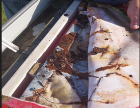
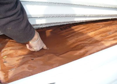
10.11B Condensation Under Roofing Underlay

Most condensation on the underside of the roof system occurs under the roofing underlay.

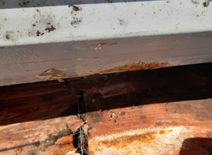
The presence of pooling condensate on the upper side of a roofing underlay indicates that the absorptive capacity of the underlay has been exceeded. Not only the underlay will be saturated, but also the ceiling structural members and insulation; mould, corrosion, and decay are inevitable. The cure is to decrease the amount of moisture entering the ceiling cavity or increase ventilation of the ceiling space.

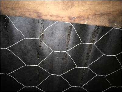
10.11C Chronic Condensation 

Chronic condensation problem caused by induction of moist air into the ceiling cavity. Although the underlay here is doing a good job of containing the surface water, the timber trusses, insulation, and ceiling below the underlay were  saturated with water.

Underlay also acts as a partial air barrier. (Rigid air barriers are also available.) Water will generally only go where gravity or air pressure takes it. By effectively reducing the space behind cladding, the underlay allows rapid pressure equalisation on each side of the cladding, thereby reducing the ability of water to enter the space.

10.11.1 Underlay Requirements 

The NZBC requires underlays under profiled metal roofing and direct-fixed metal wall cladding on lined residential buildings to be both permeable and absorbent. 

Underlays fixed to the dry side of a lined drained cavity may be permeable and non-absorbent. 

Underlays are not required in unlined structures, but in such cases non-permeable, non-absorbent underlays such as foil are typically used to increase reflectivity and to minimise condensation.

In some wall and roof applications, the underlay is required to be Fire Retardant with Flammability Index ≤5 when tested to AS1530.2. Refer NZBC C/AS3-AS6, clause 4.17.8 

Underlays designated as self-supporting can be laid without support at spans up to 1.2 m.

Other requirements for underlays vary for different cladding systems, but the important features of absorbency, permeability, water resistance, tensile strength, edge tear resistance, PH, and durability are important to comply with the requirements of the NZBC.

The Code of Practice recommends synthetic self-supporting fire-retardant underlays for residential roofing applications.

10.11.2 Types Of Underlay 

Apart from their fire retardance and ability to self-support, underlays are classified according to their absorbency and permeability.

Permeable and Absorbent:

  • Kraft paper-based — bitumen impregnated paper
  • Synthetic — 2 or 3 layers, using permeable synthetic film strengthened by sandwiched non-woven fabric.

Permeable, non-absorbent:

  • Synthetic permeable non-absorbent underlays are mainly used as wall wrap inside a drained cavity or with direct fixed absorbent claddings.

Non-Permeable, non-absorbent:

  • foil — Reflective aluminium foil over a flexible substrate. These can be either double-sided or white-faced.

10.11.3 Underlay Usage 

In lined buildings and dwellings, an absorbent permeable underlay is required under metal roofs. The same applies to direct-fixed steel wall cladding, but underlays used behind a drained cavity are not required to be absorbent.

For aesthetic reasons, a foil-faced (or white-faced) vapour check layer may be used in unlined commercial or industrial applications to reduce heat radiation from the roof cladding and provide enhancement of light. For insulated applications, foil is normally used as a vapour check under the insulation and an absorbent permeable underlay used above with a 20 mm gap from the roof cladding.

On non-residential dwellings, profiled roof-light sheeting running in continuous lengths from the ridge can have multiple skins to avoid condensation dripping from the sheeting or plastic sheet with a spacer can be used to lessen condensation. Roof underlays should not be laid continuously under translucent roof or wall cladding.

10.11.4 Underlay Durability 

NZBC Clause B2.3.1 requires building elements that are non-structural and are moderately difficult to replace to have a durability of 15 years. It also requires building elements that are part of a building system and are difficult to replace to have the same durability or to be designed so materials with lesser durability can be replaced without removal of more durable elements.

Compliance with NZBC B2, therefore, requires roofing underlay to have durability equal to that of the roof cladding and no less than 15 years.

For durability reasons, the roof underlay should ideally finish on to an eaves flashing, so that the underlay is not exposed to UV in the long run or be able to flap or vibrate in the wind.

10.11.5 Installing Underlay 

Underlay can be laid vertically or horizontally. Side laps must be a minimum of 150 for roofs and 75 mm for walls; end laps must be a minimum of 150 mm for both roof and wall cladding. At the eaves, the underlay should terminate on the upper side of the eaves flashing or overhang fascia by no more than 20 mm.

The COP recommends that all underlay is terminated at the ridge, and if not it should be slit or slotted to allow passive ventilation of the ceiling cavity.

The COP allows roof and wall underlay to be laid either vertically or horizontally in all cases. However, that is in divergence with E2/AS1, so it is advised for buildings within the scope of E2/AS1 (ie, buildings designed within the scope of NZS 3604) that the requirements of the local TA is sought before diverging from E2/AS1.

Rips smaller than 75 mm on walls or roofs can be repaired using a compatible flashing tape, but roof underlay damage greater than this requires a new piece of underlay captured by the cladding fastenings.

Flue penetrations must have a minimum distance of 50 mm from the outer liner to any underlay or flammable material.

E2/AS1 requires self-support underlay laid horizontally on support to be used at pitches below 10°. That is not a requirement of the COP as underlay support is no substitute for good ventilation design and effective weathertight details.

When using vented battens, the underlay should be positioned on the upper side of the batten, directly under the roof cladding. Having the underlay directly under the roof allows the battens to vent the roof cavity directly and allows the underlay to perform its normal design function; putting roofing underlay under ventilated battens impedes roof cavity ventilation

With re-roofs in any material, it is not acceptable to lay a new roof over existing underlay or underlay support, unless the latter is in “as new” condition. See  14.20 Fixing Aluminium Sheeting.

Wall underlays must have a minimum side lap of 150 mm, and an end lap of 75 mm. Wall underlay on a drained cavity should be on the dry (inside) face of the cavity, and be rigid enough to restrain wall insulation from contacting the cladding, or have secondary strapping to achieve such.

10.11.5.1 Horizontal Laying 

Horizontally laid underlay must be supported if used under long-run metal roofing, unless both edges are supported by purlins. Under metal tiles, self-supporting underlay can be laid over the roof trusses at spans up to 1.2 m.

Underlay laid horizontally must be laid starting at the lowest point of the roof, running over the bottom purlin and must overlap into the gutter by a maximum of 20 mm to prevent wicking. When an eaves flashing is used the underlay should terminate on the downslope of the flashing.

To lay roof underlay horizontally, more than one roll can be progressively unrolled, one roofing sheet width at a time. Running multiple rolls straight can, however, be difficult in windy conditions.

10.11.5.2 Vertical Laying 

The laps on vertically laid roof underlay may face in either direction, as the direction of lay is usually dictated by construction sequencing or wind direction at the time of laying.

The bottom end of vertically laid roof underlay must overlap into the gutter by a maximum of 20 mm to prevent wicking. When an eaves flashing is used the underlay should terminate on the downslope of the flashing.

10.11.5.3 Underlay Support 

Self-supporting underlays in lined roof spaces may be laid unsupported at spans up to 1.2 m. Other underlays must be supported. Underlay support may be safety mesh, hexagonal galvanised wire netting, builders’ tape, or other suitably strong and durable material.

Safety mesh must be designed and installed to comply with the requirements of the AS/NZS 4389:2015

Corroded galvanised safety mesh and wire netting can be damaging to any metal roofing and especially to pre-painted aluminium. Pre-painted aluminium cladding must be protected from contact with potentially corroding steel including netting, staples, or fasteners, See 14.20 Fixing Aluminium Sheeting

10.12 Additional Information 

10.12.1 Cold Roofs 

With cold roof construction, the under-surface temperature of the metal roofing will at times be quite low, so the primary tool of managing condensation is controlling the concentration of water vapour in the attic space. Some condensation is inevitable, and it must be managed to ensure the wetness is not excessive in either degree or duration — allowing moisture to accumulate.

In typical cold roof construction, the insulation is at ceiling level and there is an air gap between the insulation and the roof surface.

10.12.2 Warm Roofs 

With Warm Roofs, the insulation is in direct continuous contact with the underside of the roof.  The most common form of Warm Roof in New Zealand is pre-formed insulation panel.  Other proprietary systems may consist of several layers with a vapour control layer on the underside.

Warm roofs do not inherently have the same natural ventilation as a cold roof, so the internal environment may require management to prevent condensation problems.

10.12.3 Night Sky Radiation 

Roof cladding absorbs radiation from the sun and the attic space becomes warmer; some of this heat is radiated into a clear sky at night.

Because all objects radiate heat to cooler objects, night sky radiation will occur when there are no clouds in the sky. The radiation rate depends on the emittance of the roof cladding.

Radiation to the sky can cause the cladding temperature to drop as much as 5˚C below that of the surrounding air; that causes dew when the surface temperature reaches dew point or frost if the temperature falls below zero.

10.12.4 The Mechanics of Condensation 

Water exists in 3 states: solid (ice), liquid (water), and gas (water vapour).


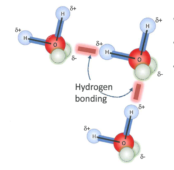
10.12.4A Hydrogen Bonding

Water molecules in liquid form bonds which create a dense material.

In ice and liquid water, individual H2O molecules bond together in a special way, called ‘hydrogen bonding’.

In gas form, the kinetic energy of the molecules has overcome these hydrogen bonds, and so the individual water molecules are free to move. The water molecule itself is light compared with other gases in the atmosphere, so it tends to migrate upwards, ie, into the roof space.

Water vapour may condense into liquid form when the concentration rises or the temperature drops. The temperature at which air can hold no more water is called the 'Dew Point'. The water vapour capacity of air is relative to temperature.


10.12.4B Shower Condensation

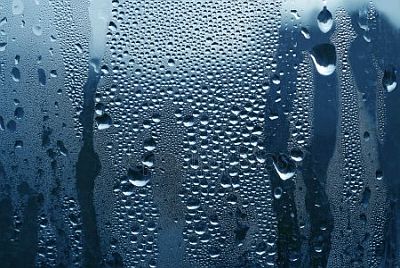
The high humidity created while showering causes condensation on even relatively warm surfaces because of the high concentration of vapour.


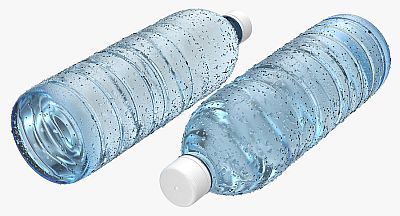
10.12.4C Condensation on a Cold Surface

In warm conditions, condensation will form on a cold surface, even when the concentration of water vapour in the atmosphere is low.


10.12.5 Underlay Standards 

Permeable underlays must comply with NZS 2295, Amendment 1:2017, as shown in Properties of Roofing Underlay, or have an appropriate Product certification such as a Codemark certificate.

Reflective foil underlays must comply with AS/NZS 4200.1:2017

10.12.5A Minimum Requirements for Underlays for Metal Roof Cladding

Classification R1R3R2R4
Grade HeavyweightHeavyweightSelf support >/td>Self-support
Type KraftSyntheticKraft >/td>Synthetic
Application  Residential or light commercial buildings>/td> 
PropertyUnit  >/td> 
Absorbencyg/m²≥ 150≥ 150≥ 150 >/td>≥ 150
Water Vapour ResistanceMN s/g≤ 7≤ 0.5≤ 7 >/td>≤ 0.5
Water resistancemm head≥ 100≥ 100≥ 100 >/td>≥ 100
Tensile Strength MDKN/m≥ 9≥ 3≥ 11 >/td>≥ 3
Tensile Strength CDKN/m≥ 4.5≥ 2≥ 6 >/td>≥ 2.5
Edge Tear Resistance MDN≥ 40≥ 100≥ 70 >/td>≥ 150
Edge Tear Resistance CDN≥ 35≥ 80≥ 55 ≥ 130

Based on Table B1 of NZS 2295 Amendment 1:2017.

  • Self-supporting (S/S) is defined as strong enough to support its own weight up to a 1200 mm span.
  • pH between 5.5 and 80.
  • Kraft based underlays shall have shrinkage less than 0.5% and maximum run-length of 10 m.
  • Synthetic underlays may have any run length.
  • Any underlay is regarded as fire-retardant if it has a Flammability Index (FI) of 5 or less when tested to AS/NZS 1530 Part 2.


10.12.6 Relative Humidity 

RH is strongly dependent on temperature. For instance, a parcel of air at 15°C and 50% RH is cooled down to 10°C. Now, the relative humidity of this parcel of air will be close to 70%, without the actual amount of water having increased.  Relative Humidity expresses how close the air is to being saturated with water vapour. Warm air can hold more moisture in absolute terms, cold air less. If the air becomes saturated (RH 100%) water vapour will condense as mist in the air or as water on adjacent cold surfaces. 

Relative humidity is a suitable measure when the risk of condensation on surfaces or mould growth is to be evaluated. 

10.12.7 Absolute Humidity 

Absolute Humidity is measured in grams of water per volume of air (grams per cubic metre [g/m3]). It is not temperature dependent and in the example above the absolute humidity would remain unchanged at around 6.4 g/m3, regardless of the temperature change.

Absolute humidity is a suitable measure if one is looking for sources or sinks of water in an environment where temperature is changing. If the absolute humidity is cycling during the day, eg, increases in a roof cavity as the temperature rises during the day. It could indicate that moisture is released by the building materials during the day and absorbed or condenses during the cooler nights. 

10.12.8 Water Vapour Pressure 

Water Vapour Pressure is more based on the fundamental physics and expresses the contribution (ie, the partial pressure) of water vapour to the total pressure of an air mix. For example, at a pressure of 1000 Pa (1kPa), the partial pressure of nitrogen may be 700 Pa, the partial pressure of Oxygen 200 Pa and the partial pressure of water vapour 99 Pa, and other gasses 1 Pa.  

This parameter is useful to evaluate moisture migration from one point in the building to another.