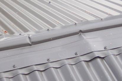
As flashings cannot move in the longitudinal direction without stress, they should have some provision for expansion and contraction, particularly at joints.
As aluminium rivets have limited shear strength capacity, riveted joints in flashings can be prone to “popping”. Popping happens due to timber shrinkage, thermal expansion, or a combination of the two. The best solutions to minimise the frequency and consequences of breaking joints are to attach flashings with sliding clips or to provide expansion or slip joints at appropriate spacings.
Transverse flashings such as head barges, ridges, and change-of-pitch flashings are particularly exposed to stress from timber shrinking as it dries. The worst can be avoided by not fixing flashings until timber moisture content is below 12%, but that is not always practical. The longitudinal shrinkage of normal radiata timber is approximately up to 3 mm per metre.
Compression timber periodically makes an appearance. Compression timber can occur in a short section of timber, which can shrink on drying up to 10 mm per metre and cause buckling of flashing and broken joints. Compression timber is hard to recognise by eye. The solutions is to wait for the timber to dry before installing flashings or, failing that, the flashings will need to be replaced once the timber moisture content has stabilised. (see 8.9 Compression Timber)
It is necessary to make provision for thermal movement of pierce fixed flashing when long lengths are used, and end laps joints are required. To some extent the spacing of expansion joints will also depend on the accessibility of the roof for inspection and maintenance, the visibility of the joint, and the consequences of leakage through a failed joint.
Inadequate provision for expansion can also cause roof noise.
E2/AS1 requires expansion joints in steel flashings at 8 metre centres for dark coloured steel flashings, and 12 metres for light, although this is inconsistently policed. The expansion joints detailed in E2/AS1 and the old Code of Practice are 3-piece methods, that have proven unpopular with installers who consider them overly complex.
8.10.3 Recommended Expansion Joint Spacing for Flashings
The table below is a general recommendation based on “typical” timber-framed structures. It is recommended that it as adhered to rigidly for ridges, hips, change-of-pitch flashings and head (transverse) barges. The need for expansion joints in aprons and barges is less critical and may be assessed by the installer.
Expansion joints in parapet caps are more critical than with most other flashings and will be subject to a later review.
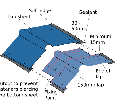
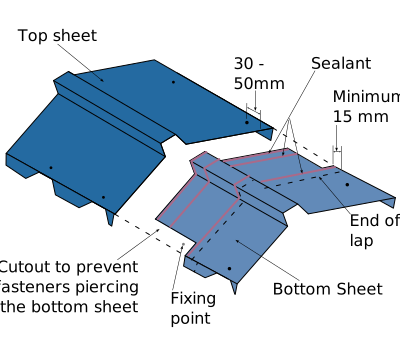
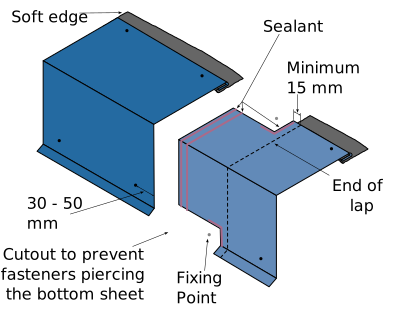
The basic design of the details shown above can be easily translated to expansion/slip joints on other flashings such as change-of-pitch flashings and aprons. The key features are that prime fastenings do not penetrate both flashing pieces, 3 lines of sealant protection are provided, and key areas such as fastener holes and the gap between the sheet end and the roof edge are given close attention.
If rivets are required to achieve a good fit of the two flashings, these rivets should not penetrate the roof cladding. In that manner, should the rivet fail in the future, weathertight failure is avoided.
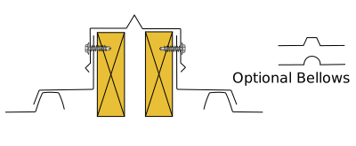
Expansion joints should be designed to accommodate contraction and expansion. Expansion joints should be detailed and constructed to a minimum height of 100 mm above the roof cladding, and curb-type expansion joints should be designed and installed to ensure drainage of the roof and to prevent any damming of water.
Wood curbing secured to the substrate on both sides of an expansion joint should be flashed with a metal capping capable of acting as an expansion joint cover.
Expansion joints have two main designs.
1. A 8.10.5A One-piece Expansion Joint to accommodate movement using a central bellows or roll that allows the flashing to be positively fixed on both sides.
2. A two-piece design to accommodate movement by the use of hemmed edges, with sufficient clearance for the expected movement.
Both of these designs are shown as a parapet following the pitch of the roof. Where this is not the case, the top of flashing should have a 3 – 5˚ slope as for all other parapet flashings. (See 8.5.3 Parapet Cappings).
Metal wall construction joint flashings that are embedded in the wall should be made with a bellows or other means of accommodating movement without fatigue and have a durability of 50 years.