
Valley Drainage
The Capacity Mystery solved
By Stuart Hayman & Stuart Thomson.
Stuart Hayman has been involved with metal roofing for many years and until recently was Technical Development Manager for AHI Roofing Ltd. He is now a Roofing Consultant and is Chairman of the Technical Committee of NZMRM.
Readers of version 2 of the NZMRM Code of Practice will have noticed a new graph 8.4.5.1.showing the catchment increasing with the pitch for three valley types, which is believed to be logical. The COP recommends using these values instead of the two listed in E2/AS1.
 With the pitch of the roof known the maximum catchment is determined from the graph.
The graph 8.4.5.1. has been calculated by allowing for 10mm freeboard and roof cladding interference.
N.B. A & B capabilities only equal if hook section A has 20mm height
Type C recommended when roof pitch s <12º
So how and why did this come about?
For decades NZ roof installers have used valley gutters to drain the intersection of two adjacent sloping roof planes on roofs of 12º or more without any concern about the catchment being drained. This has been reasonable because cases of valley gutter flooding have only occurred when blocked by debris. 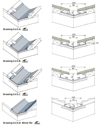 The assumption has been made that the slope of the gutter allowed water to run away more quickly than it could accumulate and empirical tests have shown virtually no limit to capacity up to a rainfall of
100mm/hr.
Empirical testing means the combination of science, observation, measurement and guesswork which typifies engineering research into very complex real-life, real-time phenomena like flow in a gutter.
When E2/AS1 was published in 2004 the Roofing Industry was surprised and alarmed to discover that conservative limits had been placed on the catchment area permitted above valley gutters, with no consideration given to different roof pitch or capacities.
Table 8 of E2/AS1 quotes the maximum catchment area for the two commonly used valley gutter widths -160 mm for metal tiles and 250 mm for metal cladding and concrete tiles, to be only 16m2 and 25 m2 respectively, regardless of roof cladding type or pitch, or gutter profile.
This erroneously implies that the width of the gutter is the determining capacity factor instead of the cross-section. Metal tiles have always used a narrower gutter because they are turned down into the valley, reducing the possibility of side splash.
However E2AS1 has a "let-out" comment which says "Gutters for lower pitched roofs or for catchment areas other than those shown " shall be specifically designed. Additional information may be found in the NZMRM COP
From section 8.4.5.of the COP
So, why is this? Where does this information come from?
The answer is that it is the end of a bit of detective work as Stuart Thomson would say, however, this one is definitely a "Cold Case", going back over 60 years, and the answers have been sitting there for anyone to discover.
The chronological history is very interesting.
- 1939, F.E.Camps takes a scientific/engineering look at water flow in flat box gutters and finds them a very complex system.
He derives empirical equations describing the flow in and capacity of box gutters with less than a 1º slope, vertical sides and a flat bottom. - 1968, Messrs Martin and Tilley publish work previously done on the same topic for CSIRO in Australia.
They worked on flat box gutters with a slope of 0-3º having discovered that Camps' equations didn't work over about 1º - They also worked on sloping valley gutters, and set up a small sloping test roof to measure the flow rate and water height in the gutter for different slopes, shapes and inflows A picture of the test rig is appended.
- 1995 Simon Beecham et al did similar work at Sydney University and used computers to attempt a more accurate model of the real situation in drains and gutters.
They confirmed the Martin and Tilley work - i.e. flow in sloping gutters is a factor of slope and gutter shape and size - 2005 E2/AS1 was published including the restrictions on valley catchment. Investigation showed that the basis had been AS 3500.3:2003. As a result copies of the Martin and Tilley report and Simon Beecham's work were obtained from Australian sources and the investigation began.
- 2007. NZMRM COP adds a catchment graph 8.4.5.1.based on the work of Martin and Tilley report and Simon Beecham's work and recalculated for New Zealand by Stuart Hayman. To have arrived at the conclusions published in the COP considerable research and investigation was necessary and is available for those interested.
AS/NZS 3500.3:1998, and possibly earlier versions, included an example of a valley with 12º pitch and gave widths for different rainfalls which appears to have remained unchanged for 40 years.
Although AS 3500 is an Australian Standard (with some parts joint with New Zealand), it has become the default document for New Zealand design.
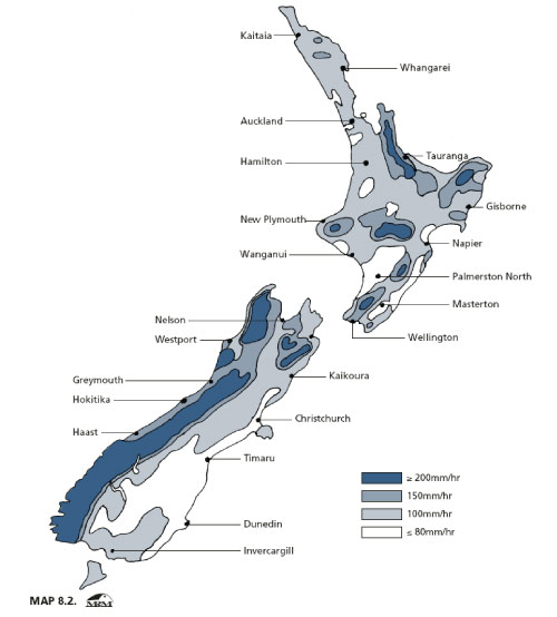
New Zealand however does not have the tropical downpours of Australia and so in New Zealand Standards we use different maximum rainfall values and a different Average Recurrence Interval (ARI) from Australia. This confuses the issue and somewhat invalidates the assumptions made by using AS 3500 as the basis for NZ gutter design.
COP 8.2.
 When calculating roof drainage where significant inconvenience or injury to people or damage to property, including building contents is unlikely the Average Recurrence Interval (ARI) used must be 10 years. e.g. due to an overflow of external eaves gutters.
When calculating roof drainage where significant inconvenience or injury to people or damage to property, including building contents is likely the Average Recurrence Interval (ARI) used must be 50 years. e.g. due to an overflow of internal gutters.
This has led to the historically rather confusing use of a safety factor of 2 by using 200mm/hr instead of 100mm/hr as in New Zealand the maximum rainfall for internal gutters.
The basis for establishing the gutter size used in the COP was on cubic capacity using the Martin and Tilley work not on width although a recommendation is made that the box gutter proportion of width to height be 4:1.
Using the design methodology adopted in the COP section 8 for roof drainage, factors are applied to catchment, pitch and cross- sectional area.
A valley gutter is defined in the COP as: A gutter at the internal intersection of two sloping planes of roof cladding where the roof pitch is 12° or greater.
The aim of previous researchers was to determine the input levels at which the water level in the gutter exceeded some safe level (freeboard) and risked overflowing the sides.
For a flat gutter this is determined by the type of outlet but with valley gutters the outlet is always an open weir which is almost impossible to flood.
As may be imagined, the flow pattern along a valley gutter with sloping sides and inflow increasing along its length is very complex and in pre-computer days researchers struggled to derive any scientific equations from this work.
The Martin and Tilley equations use the rainfall, gutter cross-section, width and slope to determine the carrying capacity which enables calculation of catchment over quite a wide range of pitches by inputting these factors.
Although this allows graphs to be generated for a specific gutter shape and fixed rainfall it does not allow production of a simple catch-all formula.
The E2/AS1 figures more or less comply with the AS 3500.3 Section 3.6 but are at the extreme conservative end of the range and do not allow for the different shape of NZ valley gutters or for any of the other four variables.
The COP published graph is still considered conservative.
.
A given valley gutter shape changes profile as the roof pitch increases which increases the carrying capacity.
However the secret is now out and the COP provides you a calculated reason not to use the limitations in E2/AS1. This does not decrease the validity of the cautions in E2/AS1 about change of direction in the plan view, or changing valley pitch along its length. Either of these significantly increases the risk of overflow and requires special gutter design if this is to be avoided.
The COP provides one example with the bifurcated gutter over a porch, 8.4.5.2. but other modifications can be designed to be used in other non-standard circumstances.