
NZMRM And Wind Load Testing: Part 2
In writing this it was not easy to reconstruct the first 8 or 9 years of life of the NZMRM Test Rig. Although the author was involved during most of its life (as an NZMRM Executive member) this involvement increased from “knowing about it” to more recently managing it and hands on “driving”. So if the earlier details are a bit hazy it is because no-one really kept records, until the last 5 or 6 years. However the basics of the history are correct if some of the dates are not.
This article is a description of the machine and how it has been and is used; its ownership, location and management/manning history; and changes in what it can do based on the changing requirements of the market. Finally a report on its current upgrade, planned to be finished by the time this is published (but held up, as so many things, by Covid-19).
What is it?
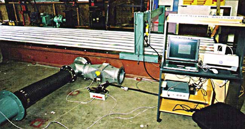
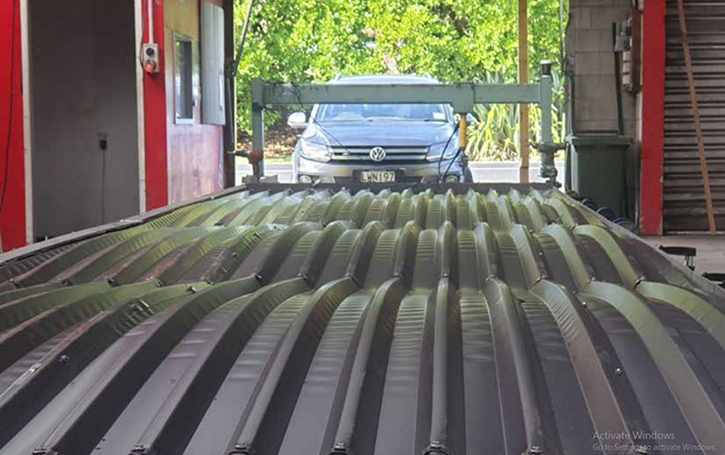
As previously stated the NZMRM test “machine”, which we call our Test Rig, has bypassed some of the earlier global methods of sandbags and airbags, gone straight to the “blow-off box”. it is a steel box 15 m long by 2.1 m wide and 330 mm deep. The sides are made of solid steel “C-Beams” as shown. This box has one end closed off and a moveable dam at the other end.
This allows the length of the actual box to vary between 15 m and (in theory) 0 m, in practice about 3 m. Inside this are 4 purlin mounts made of steel which carry the timber purlins into which the test roofing is fixed or attached. This allows for 5 spans, which is what NZMRM have traditionally used, and of course by removing purlins you can have 4, 3, 2 spans or indeed a single span. So this allows purlin spacing maxima of 3.4 m(not quite 3.5 by an original oversight); 4.5 m; 6.4 m or 7.5 m and anything less, depending on how you arrange the spaces – NZMRM use end spans of 2/3 main to allow for roof edge effects and so length required for 5 unequal spans is 4.33 x main span required.
Originally the “box” was formed by the two 15 m side C Beams, and the ends, located directly onto the floor, and screwed down over sealing material. This of course meant it wasn’t very easily relocatable, although it does seem to have moved about quite a bit in this configuration in its early days.
The pressure is generated by a rotary fan driven by a motor whose speed can be varied.
The purlin mounts were originally clamped onto the horizontal rails, and located by lifting and moving manually. We now have these with rollers at each end and they are locked to the rail by car jacks under each end. This significantly reduces the amount of time and effort needed to change spans.
Cyclic testing is where the pressure inside the box fluctuates quite rapidly between full pressure and a reduced pressure, and is supposed to simulate the action of fluctuating wind pressure, specifically as occurs during tropical cyclones (increasing in one direction, dropping off, then decreasing in the opposite direction) but also any other storm or gale wind variation pattern. This effect is produced by a shutter valve at the air inlet location which drops and raises pressure quite quickly. This is not frequently required in New Zealand.
History
The test rig was built around 2000 by A and S Engineering for Roofing Industries to a design by John Yolland and Stuart Thomson (probably based on the requirements of the Australian standards mentioned in Part 1), and was located at the Roofing Industries factory in Takapuna. It seems that in the succeeding 5 years it was “borrowed” by NZMRM members for testing carried out by John and Stuart around Auckland, in spite of the difficulty of relocation. (Easier times!)
In 2005 NZMRM purchased the rig from Roofing Industries, and then had to look for a permanent home for it. Several possibilities were considered, including NZ Steel at Glenbrook, Auckland University and Wintec at Hamilton. It did spend some time at Wintec and was there and used during the RANZ conference in 2005. The rig then visited (in some sequence) Dimond and Calder Stewart in Penrose. Also in this year the control system was originated by Mastec, based on Labview. Many changes to this were to eventuate.
No agreement with Wintec or any other possibility, transpired and it was relocated “temporarily”, still in one piece, to a shed in Great South Road Penrose, rented at the time by Pacific Coil Coaters. It seems to have been there from 2005 to 2008, during which time a number of alternative locations were discussed, again inconclusively. During this time the operation was computer operated by John Yolland, and physically by Ross Simpson and managed by Phil Meyers. A number of generic tests were done to develop Load Span graphs for the Code of Practice, and the rig was quite busy.
In 2008, to make it more portable, it was refashioned by Phil into 3 separate sections, with a floor, levelling screw feet and wheels. This meant it did not need to be attached to the floor and could be loaded onto a normal truck for movement. This also means the quality of the floor is fairly unimportant. This was zinc painted for protection, which has lasted well.
In 2009 the PCC location was closed and we had to look for alternatives. For a while it was used at AHI Roofing, with excursions to Taupo and possibly other places. Ross found a very suitable building in Huntly, on the main road, with access front and rear, which was then rented from Goodman Fielder, who at that time leased the entire block of buildings from the Shands family (an old established Huntly business).
It has been there ever since, and in the last 10 years has tested corrugate and trapezoidal top fixed, tray and clip fixed rib roofing, Australian clip fixed roofing, two lots of garage doors, steel and aluminium and clear roofing, SIPS, metal tiles and several other non-standard products for the major NZ manufacturers, and others. Static and cyclic tests have been performed.
The Testing Outcomes
The requirement is to test wind uplift resistance – Uniformly Distributed Load (UDL); initially only to Serviceability Limit State (per AS 1562.1) as a static single pressure load, and much more recently to Ultimate Limit State. It was also needed to be able to test cyclic wind pressure resistance, initially to more than one protocol but then only to the Low-High-Low programme developed by the Cyclone Testing Station to more accurately predict performance in tropical cyclones in the D regions of Australia, but not used in New Zealand. We have tested to all of these and some quite long programmes to L-H-L. (This does require knowledge of a target set by static testing, and is very time-consuming).
We also test concentrated (point) load to determine the trafficability of roofing. This includes measurement of deflection in up to 6 locations. (This equipment has also been upgraded).
The Method.
This has basically remained the same with improvements to allow for increased pressure. The purlins are mounted at the appropriate spacing. The dam is sealed in placed at the sheet length. Depending on the width of the product sheet and the nature of the profile, the box top is covered with part sheets at each side, and one or two (or more for e.g. narrow tray) full sheets in the middle. The sides are clamped down as well as possible, and the sheets fixed in the normal way for the product and the fastening pattern being tested. The aim is to give at least one sheet fixed more or less as it would be on a roof, unaffected by the box side clamping. At each end the sheets are fixed more densely to avoid end blow-off (which does create an anomaly and is why we observe the central purlins).
Using the computer, the pressure is gradually increased and the product observed for serviceability failure, as defined, round the fasteners. Pressure and observation is recorded manually. If deflection is being measured this is also recorded. Serviceability failure is noted. If Ultimate failure is required then the pressure continues to be increased until the sheets are damaged to the point where no more pressure can be exerted, and the sheets have separated from the purlins in at least one place. This is normally when the sheet blows off over the screws or along an overlap.
Operation and Charging
This rig is owned as a service to NZMRM members and apart from a daily charge, only recovers costs. Operation requires one person to control the system using the computer, and a minimum of one other person to fix the roofing. As lengths increase 2 or 3 people are required to actually handle the sheets, which can be very heavy. The fixing time also decrease proportionately with more people. These people are all charged out at cost.
If the results require certified depreciation to AS/NZS 1170 then a CPEng (Chartered Professional Engineer) is needed to do or verify the results. NZMRM has used one person for this for 10 years.
The Control System
This was developed early on in the piece by Mastec after discussions with John Yolland, and it has been upgraded several times, and recently undergoing a major one to cope with the increased pressures. This has been running on several computers with different (now obsolete) operating systems. One of the pictures shows the original desktop PC. This was stolen and replaced by a laptop of some sort (also stolen). Since then we have uses two pairs of (oldish) laptops, taken away from site and one each kept by different people. We now need a further upgrade (to Windows 10!) to cope with the most recent programme upgrade.
The programme allows control of the power fed to the variable speed drive to control the fan, at the same time recording the pressure inside the box. Several relays connect the test rig and the motor to the computer. It has produced, with varying degrees of success, plots of pressure against time, or against deflection. In practice, and started by John Yolland it has proved better to record what happens as the pressure is increased. This also records the concentrated load and deflection.
The Upgrade
During this time the maximum pressure achievable (subject to leaking) has increased from 6.5 to 7.5 to 8.5 kPa by tweaking the variable speed drive. We have learned to minimise leaking by changing the way the sheets are clamped to the sides and the main leaks now occur from the dam end. We have reinforced the floor underside supports significantly.
In spite of this, ever increasing demand for higher and higher pressures, has required a significant overhaul and upgrade, which is being completed as this is written.
This upgrade includes a new and bigger fan with a more powerful motor and, to cope with the increased pressure, floor thickened with 4 mm Corten and painted with anti-corrosion, anti-slip paint, side clamping improved, end dam completely remade with hinged base to improve sealing, and roller movement along rails, like the purlins. This no longer needs to be lifted over floor joints.
The control system has been updated and again tweaked. The aim is to be able to generate testing pressures up to 15 kPa (which depending on whose calculator you use = 750 or 550 km/hr, really?)
In addition, those who have been there will be pleased to learn we are also improving the interior of the building. Taking the leases back by the Shands family has meant some much needed maintenance (and also higher rent).
The Future
As it enters its 3rd decade completely rebuilt, and with a better understanding of the increased demands for testing, it can continue to provide a service the NZMRM members and their own customers for another decade at least.