
NZMRM And Wind Load Testing
Part 1: Setting the scene.
Wind events and cladding.
The primary purpose of a roof (or wall) is to keep rain and wind out of the building it is over or around. This means it must stay on the building regardless of whatever the weather throws at it. This is generally taken to mean wind and rain.
In Australia this weather includes tropical cyclones, which have had very destructive outcomes over large areas. In New Zealand it includes all our “regular” weather, which located in the middle of an ocean is not cyclonic, but we do have severe wind events which we don’t expect to damage buildings. In spite of this we seem to accept damage from the occasional high velocity “twister” or “tornado” which is usually very localised (down to a few houses). These do have wind-speeds much higher than the normal run of storms, and the circular motion can lift off otherwise robust roofing. It can also include earthquakes.
So we do need to be able to determine wind resistance of our various cladding components.
There are a number of variables that affect the ability of a roof to withstand local wind uplift pressure.
The variables in cladding
These relate to the roofing product and its installation as separate variables. The product base is characterised by the metal, its thickness, and its tensile strength. This may be rollformed into one of many profiles. This then fixed to a structure which is basically part of the building. The roof structure is typically longitudinal members (rafters) attached to the frame of the building, and then horizontal cross members (purlins). Both rafters and purlins may have variable spacing to provide different levels of support. The product is fixed to the purlins with fasteners which go through a rib into the purlin (top-fixed) or held to the purlins by one of two main clip fixed/secret fixed methods. Top fixed roofing may be fitted with load spreading washers (LSW) to increase uplift resistance
Testing
In order to determine if a roof (or wall) will withstand the wind load in a specific location it is obviously desirable to test the proposed setup at a wind pressure similar to that to which it will be exposed to in practice, rather than just waiting to see if it fails.
There are two test concepts –
Calculate the pressure at a particular location on a structure, expose a test set-up of a suggested configuration to the calculated wind pressure and see if it passes. If it does then it is suitable; if not determine the pressure at which it fails, or upgrade the configuration in some way (thicker, more fasteners).
Or test the suggested configuration to failure at increasing spans. This will advise the span at which the product can be used in a location with this wind pressure. This has been the process used in NZ.
Usual test procedure is to take one profile, made with one material (metal, thickness and strength) and test one fixing method and then vary the purlin spacing to generate a Load/Span Graph. Several linked variables may be on one plot e.g. with and without LSW, different fastener density (possibilities are determined by the profile, e.g. how many ribs?) and perhaps material thickness. Depending on the profile, more than one fixing pattern may be possible. Normally however each plot is for one set-up of everything with purlin spacing the only variable.
In reality there is more than one imposed external load on a building – wind pressure uniformly distributed over the exposed face (UDL) which may be into or away from the cladding, concentrated or point load in one location, typically roof traffic but may be other localised loads, and snow loading, also UDL but only downwards. Here we will discuss primarily wind loading. In considering wind “uplift” removing cladding panels we are looking effectively at suction upwards/outwards. Since in practice it is difficult although certainly not impossible (check Intertek) to create suction over a large area of cladding, we have used various ways of applying uniformly distributed loading to the underside of the cladding and determine resistance of the material to being blown off or over the fastening system. For much of the time during which testing has been carried out in NZ we have been looking at permanent damage round the fasteners for top fixed roofing (termed Serviceability failure as the product may remain in place but not fulfil its function of keeping water out) and actual removal of the cladding for secret fixed roofing (termed Strength or Ultimate failure).
The demand
The local test requirement “marketplace” has been a volatile one. For quite a period in the 2010s the emphasis was on using greater purlin spacing. Then we saw the use of tray roofing on purlins instead of ply decking. Both of these produced a demand for extra testing.
More recently there has been a demand for Ultimate failure data after Serviceability for top fixed roofing, and some secret fixed roofing has properties which may allow declaration of Serviceability failure as well. There is currently a demand for much higher wind uplift resistance (although wind conditions haven’t actually changed) and as we shall see when we get to the NZMRM Test Rig this has created a need to upgrade the equipment. Some of the other global test methods produce ultimate failure only – destruction.
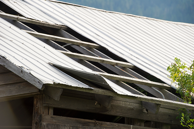
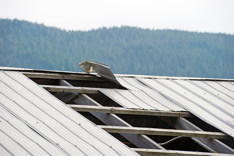
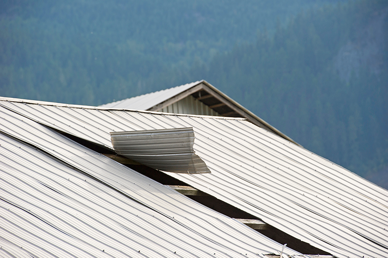
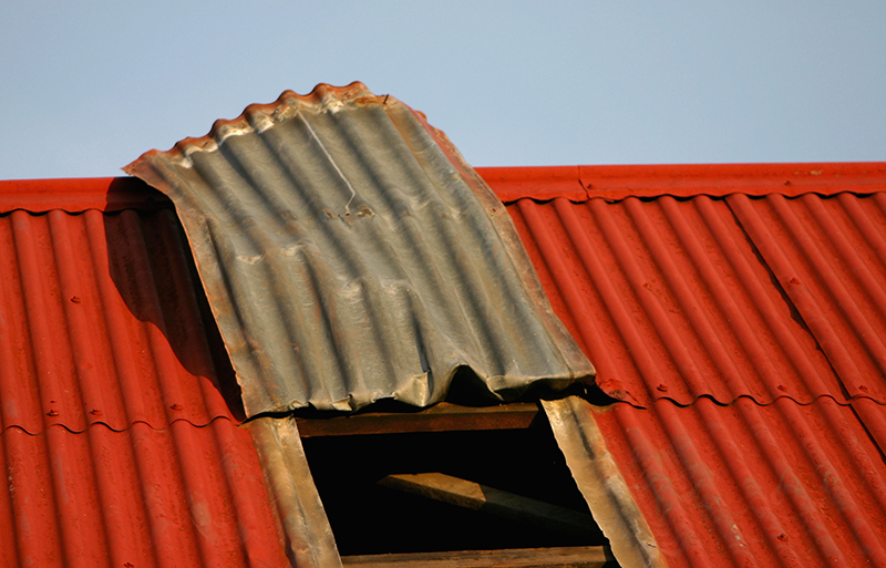
How wind blows things off
Actual wind blows down on one part of the building creating inwards pressure and then creates upwards or suction pressure on an adjacent area. This what blows the roofing off. Creating a low-pressure (suction) test area over cladding, while not impossible, is not very practical, and so we simulate this by applying upwards load underneath the cladding and determining the effect on the fasteners, which are effectively lifted from the supporting purlins by the sheet itself. For this purpose the supporting structure and the fasteners are regarded as rigid, although in real life situations this is not always the case, and roofing can come off more less intact, separated from the building. It is the case that in real life, e.g. blown-in garage door, internal pressure also can occur. The net total pressure effect is the same. Although “blowing off” seems to be across the roof instantly, in fact it is a rapid sequence of failure starting at one place, usually the periphery.
Testing globally
So, how do we actually do the testing? Over decades various methods have been used around the world to simulate wind action on building cladding. All of these are by necessity a compromise to some extent. Investigating the internet shows people today using a box filled with water; loading sand onto the underneath of an inverted roof, and using combined suck and blow devices. Probably the most similar to real life would involve using a very large wind tunnel to house an entire test roof, or possibly an aircraft engine (Florida). These all suffer from various disadvantages, not least the cost of the equipment and the difficulty of accurately and quickly measuring the actual pressure, and also the difficulty of generating the very high pressures currently required in NZ without destroying the test equipment. In a number of cases it looks like the test is a single one to destruction.
In Australia and New Zealand, we have used sandbags on upside down roofing, then airbags underneath the installed roofing. The late Stuart Thomson spent many hours testing a whole range of products with airbags for NZ Steel in the 1980s. The advantage is that the pressure is applied as incremental self-contained load sources and no specially pressure resistant substructure is required. The disadvantage is that the pressure is not directly applied underneath the fasteners and it is not very realistic at the actual point of connection between the fastener and the support structure.
The Airbox
More recently, and in New Zealand since about 2000, we have used an “airbox” in which the product to be tested is fixed as it is to be installed across a steel box 15m x 2.1 m x 0.5m, forming the top of a closed box. Air pressure is applied to the box and so the underside of the sheet, until something happens. In Australia there are at least two of these units, one publicly available at the Cyclone Testing Station in Townsville, (part of James Cook University). This unit originated in the 1970s following two cyclonic wind damage disasters, and became the CTS in 2002. They have an airbox 10m x 2m x 500mm and an airbag tester also. Air bag testing requires less structure and is still used in Australia (and perhaps elsewhere). We understand that BRANZ also have a smaller unit.
Standards in Australia and NZ
There are a number of standards globally which cover how to calculate wind loads and how to test things for their capacity to withstand these loads. For Australia and New Zealand the relevant standard calculating wind loads is the joint standard AS/NZS 1170.2 Structural Design calculations Part 2 Wind Actions. As in the simpler NZS 3604 the wind load on a section of a building is determined by a number of factors – location and so local wind speed, topography, sheltering, and the shape and location in the building of areas of cladding. Having done a calculation you (engineer) add a local factor Kl which can be up to 3 times the nominal pressure on the building. This has been created by successive failures of less conservative calculations.
Now having calculated the loads cladding is required to withstand – and noting some of this in NZ is related to isolated extreme wind events, which climate change may or may not exacerbate – we need standards to govern testing. As normal we have Standards which tell you how to test stuff and (in this case ) one to tell you what numbers you need from the testing.
These are all Australian only, although NZMRM have had input into the latest version. The test methods are in the AS 4040 series. 4040.0 is the covering general Standard, 4040.1 covers point/concentrated load testing, 4040.2 is wind uplift for non-cyclonic regions, and 4040.3 cyclic wind load testing for cyclonic regions. All of these are dated from 1992 apart from Part 3 which was updated for the new Low-High-Low cyclic test in 2018.
The main Standard covering roofing in all its aspects is AS 1562 Design and Installation of sheet roof and wall cladding which actually has parts for metal roofing (Part 1), plastic (Part 3 2006, joint AS/NZS) and fibre cement (Part 2 1999.) AS1562.1 started life in 1992 and after several attempts during the 2000s and 2010s was eventually revised seriously in 2018. NZMRM was involved in the committee doing this, and not having it as a joint standard (which was the original intention) allows us to use parts selectively.
And – the NZMRM Code of Practice for Metal Roof and Wall Cladding. Created in 2003 and now in online only version this has contained information about wind load testing according to Stuart Thomson and John Yolland all this time. In the end what we were being asked to do and what was in the COP deviated. This has been rectified and Section 17 now contains specifications for testing concentrated load and wind uplift based on mostly the above Standards, modified according to NZ practice and experience.
Next time – The history of testing by NZMRM, and the NZMRM test facility, past and future.