
Designing smart with profiled metal roofing.
It is easy when designing a building to leave the roof cladding until last; however, consideration should be made at the outset of design of the Kℓ pressure coefficient factors, which apply to roof cladding and the purlins at the periphery of all buildings.
Some engineers are now designing specifically for the wind pressures, but just how much the site orientation, topography, location and roof pitch of a building affects the design requirements is not universally appreciated by designers and some engineers.
As an example:
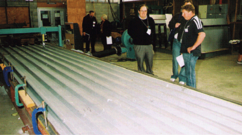
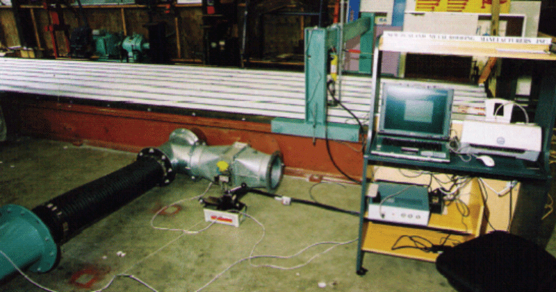
At a wind engineering workshop in Wellington recently, John Holmes (one of the main drivers behind AS/NZS 1170.2) made available copies of a series of worked examples on AS/NZS 1170.2. The following is quoted with acknowledgment to John Holmes and Cameron Smart – Engineering Projects Manager IPENZ, Engineers New Zealand.
While the details of the calculations are directional, these have been omitted and the worst case, south-west (SW) Direction is used as a means of illustration.
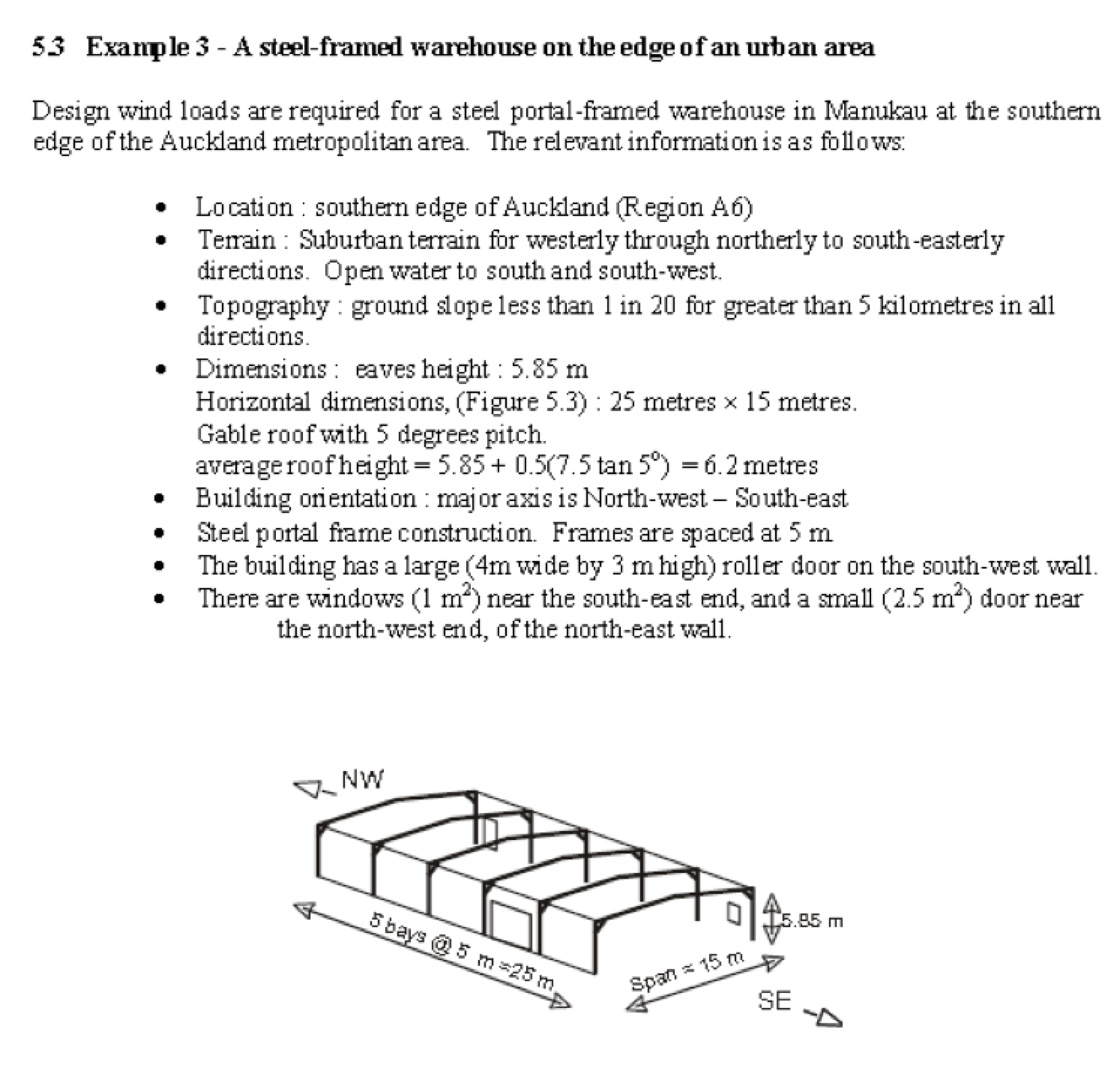
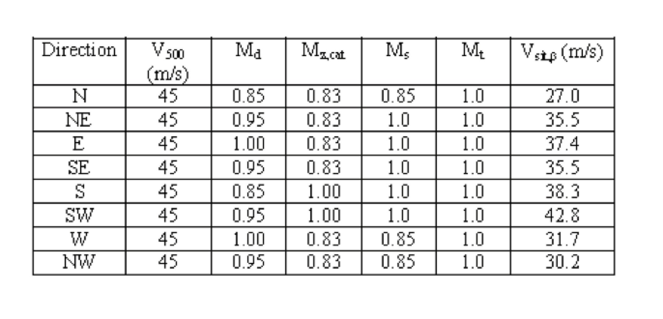
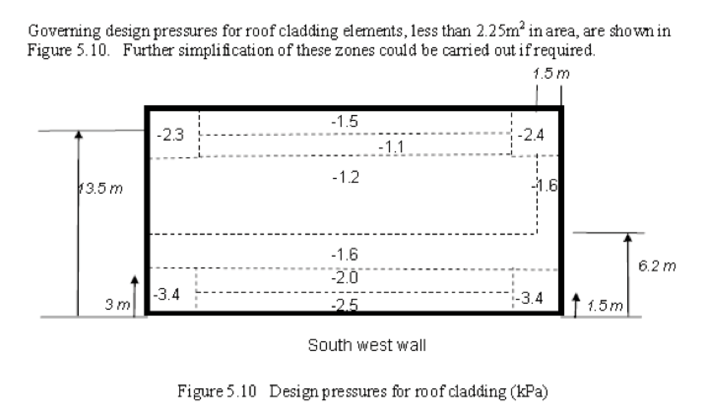
For the body of the roof, the wind design speed is given as 42.8m/s (see table above), which equates to the 1.1kPa on the area shown in Fig. 5.10.
While the Kℓ factor in the corners of the building is given as 3 in AS/NZS 1170.2: 2011, because the various factors concerned, this translates to 3.4kPa as the worst case scenario on the SW Wall.
The question could be asked why the Kℓ = 3 factor was ignored in NZS 3604 and the answer from Roger Shelton, Structural Engineer BRANZ Ltd, who provided the engineering data for the NZS 3604 revision in 2011 was:
It was “ignored” in 3604:2011 because 1170.2 hadn’t been amended at that stage. In any case the area RC1 is small enough to ignore in 3604 scale buildings. I agree that for commercial sized buildings it may be a concern.
To apply the Kℓ = 3 factor from AS/NZS 1170.2 the roof has to be < 10° (i.e. a roof ≥ 10° is exempt). However, from wind tunnel tests conducted in UK, BS 6399-2 gives a maximum Cpe of 2.6 at the corners of a building, but extends this to include roofs with a 15° pitch.
This document is very detailed and gives hundreds of precise Cp factors unlike AS/NZS 1170.2:2011 which uses only factors of 1.5, 2, and 3.
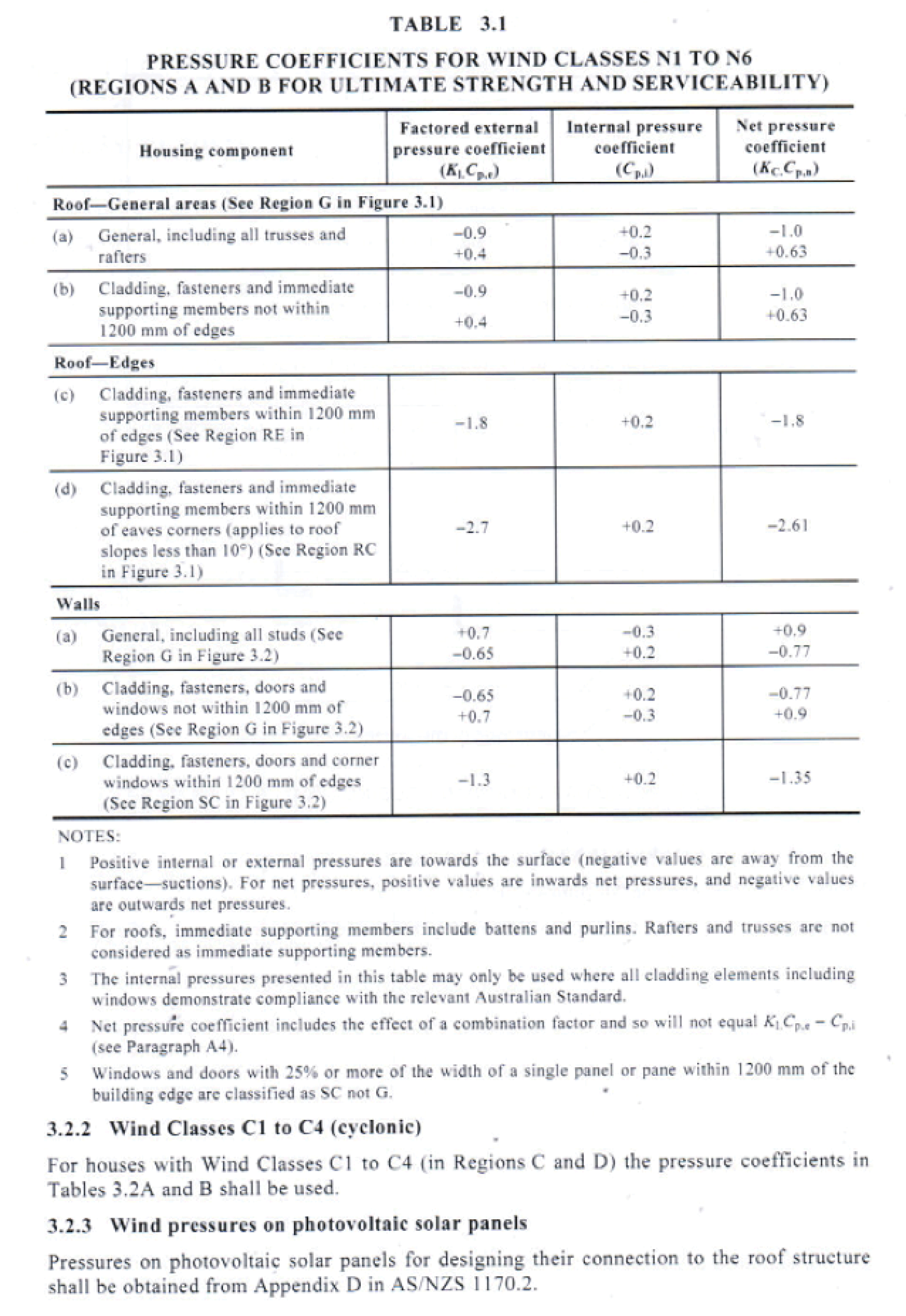
Australia’s Standard AS 4055 ‘Wind Loads for houses’ takes a more pragmatic view and gives a Kℓ peripheral figure for distance of 1.200m, but still has different pressure coefficients for the corners of the roof and the walls. It does appear to include the roof corners, no matter what the roof pitch is, but also limits the combined net coefficient to 2.61 for non-cyclonic areas (see Table 3.1 of AS 4055, below).
The question could be asked why have the changes to AS/NZS 1170.2 only happened now and what prompted the change? It is believed that it occurred because a number of steel framed buildings were destroyed in the recent cyclones in Australia but my own investigations into cladding loss or purlin failure, points to the fact that these buildings did not follow the recommended fastening patterns and purlin spacings for the thickness of the material already existing at the time. It is well documented that roof cladding failure starts at the barge, and often at the corners, and is an incremental failure not a catastrophic one as it sometimes appears but has not been widespread enough to cause any great alarm in New Zealand.
We are, however, bound by the changes made to the loadings code and must design within its requirements but not to the extent that results in over-design of the whole roof fastening system. So to design smart we must know what to do. There is no one size fits all but an appreciation of what can help is what this article is about.
It could be said that to get over the Kℓ = 3 hiccup, it would pay to only design roofs of 10° or greater, or to have parapets, but that would be complying with the Standard and not necessarily understanding the way wind works.
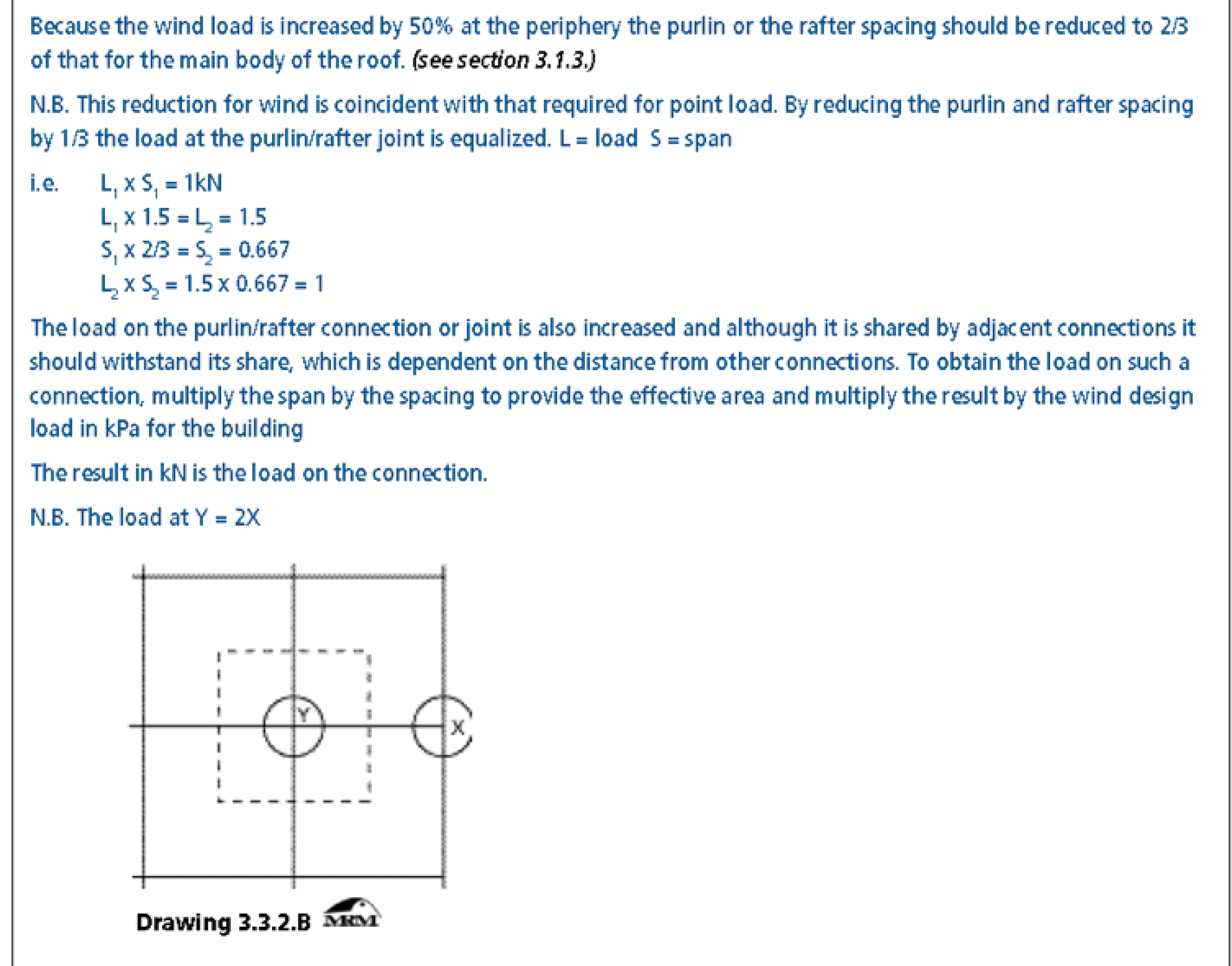
Quite a saving can be made by first reducing the end portal spacings so that purlin spacing can remain constant and still comply with a higher loads experienced at the periphery. Another way is to use a splice to provide added strength at the end spans and also over 100% increase in UDL performance can be achieved by using a purlin of the same size but of a greater thickness and 25% by increasing the number of braces.
It is a given that the purlin spacing at the eave and at the gutter line be reduced to 2/3rds of the rest of the roof, not only for the performance of the sheeting but because of the increased load at the periphery. We would like to think this is always done but…..
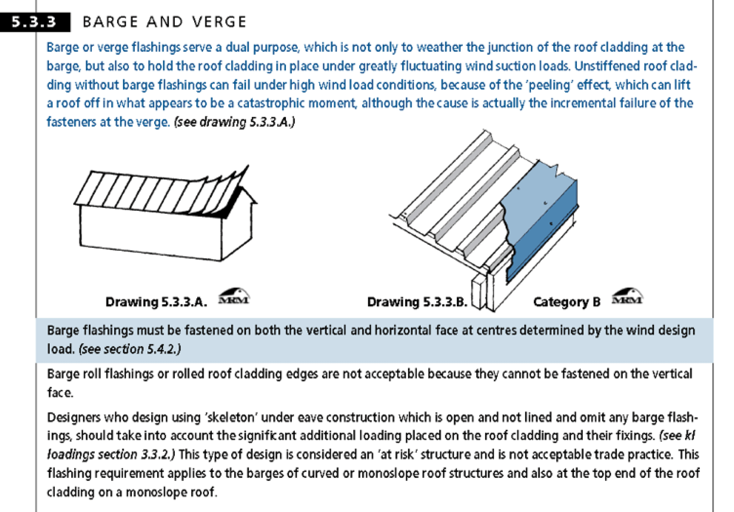
Of particular importance are the corners of the roof of the building when the pitch is less than 10°. AS/NZS 1170: 2011 (our New Zealand loadings code) calls for a much higher load factor of Kℓ = 3 for roof and wall cladding corners; this does not need to be a problem because the tested wind load for corrugated and trapezoidal profiles and their fastening patterns are given in Section 3.9 of the NZMRM Code of Practice. What it means is that the corners of roof and wall cladding fastening pattern should be increased but, more importantly, barge flashings require double fixing.
The CoP already has this to say:
This needs to be spelt out on the drawings and not left to the roofer’s discretion. There is sufficient information provided in the NZMRM Code of Practice or the manufacturer’s literature for the designer to be more explicit in what he wants. Engineers can (and should) do this in their own best interest, as well as their client.
Speak to roofers and you will often hear – ‘We never do it that way’ or ‘ We always do it that way’ but they seldom know the reason why.
One common error that is made by designers and installers alike is to increase the number of fasteners on the gutter purlin; whereas, the highest load is on the penultimate purlin. This is because the end span is normally reduced to 2/3 and the tributary area is greater on the penultimate span. There should be no worries about trough fixing as, unlike roofs, wall lengths are limited and gravity and sealing washes take care of the water. They don't leak -trough fixing is commonplace for roofs in Europe.
If you are not already specifying LSW (Load Spreading Washers) then have a look at the increased performance that you can get from their use.
All metal cladding profiles have been tested for wind uplift and point load.
It is worthwhile doing the sums on using thicker cladding material at larger purlin spacings as this not only saves on fasteners and purlins, but provides a roof which most times you can walk on with care. A base metal thickness of 0.40 mm in steel and 0.70 mm in aluminium maybe OK for walls, but for roofs it pays to have a look at the performance of 0.55mm steel or 0.90mm aluminium and deeper rib profiles. Roofs are point load tested to 1.1kN which can easily be exceeded with a man carrying or sharing an air conditioning unit to install. Roofers are often dismayed to return to their newly laid roof to find the amount of damage done in the vicinity of the air conditioning unit or solar panels.
If there are air conditioning units or solar panels that are to be installed, they have to be serviced so it pays to install walkways beforehand. Damage often occurs to a new roof by the installation of such units on the false assumption that men carrying them can walk indiscriminately on a metal roof. However undesirable as it is to place service units on the roof, designing for the end use of the building is part of the designers’ responsibility.
It pays to forget fibreglass sheeting in the end bays if possible because, unless the heaviest fibreglass 3600gsm is used, the uplift performance of thinner fibreglass sheeting does not equal that of the metal roof cladding. Canopies require a lot more consideration as well.
Secret fix profiles have the advantage of long lengths and a built-in expansion provision, but they do not perform as well as top fix roofs under high uplift loads. We know there is an advantage in venting a roof to obtain a reduction in the wind uplift load but quantifying it is a bit of a problem. Because of failure in the Pacific islands these profiles are required to be top or pan fixed, which negates the advantages of secret fix. The disadvantage of top fix roofs is that the fastener is exposed. Not many fasteners can match the substrate corrosion performance and stainless steel fasteners are considered (at the present time) to be incompatible with the Zincalume cladding.
The isolation technique of separation by using oversized holes appears to be working but the jury (MRM technical committee) is out on that issue. The cost of the fastener versus the cost of installation and roof cladding warrants the use of class 5 screws which are the best available and include aluminium fasteners for timber and stainless steel screws.
Low pitch and long lengths for metal cladding offer cost effective design solutions but here is a fine line between over-design and under-design; cost per m2 is probably what the client wants to know. This is not an easy job but then anyone can do those!
The climate has changed on liability in these areas and we need a tighter specification by the designer in areas such as flashings and fixings. Understanding what is required is part of the service that MRM provides to the industry.