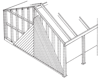
Fixing Horizontal Corrugate Cladding
The cladding contractor should inspect and approve the standard of framing before the commencement of any cladding installation. The use of 0.40 mm coated steel cladding is likely to show any deviation in the line of the framing and 0.55 mm is, therefore, the preferred choice.
The support centres should be reduced for horizontal cladding and a minimum flashing thickness of 0.55 mm for steel or 0.9 mm for aluminium should be specified. The width of the supports will be determined by the method of jointing and secondary framework may have to be provided, with all support fixings being counter-sunk.
Fix horizontal cladding in the pan as that provides a stronger, more economical and aesthetic fastening than crest or rib fixing. The number, spacing and the position of the fasteners are determined by the wind design load for the building. See Wind Load Span Graphs.
For aesthetic reasons only, or where the cladding is at eye level, the number of fasteners may have to be increased to every second corrugation for corrugated steel, and one primary fastener placed at every trough and secondary fasteners at 500 mm centres for other profiles.
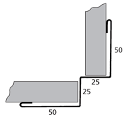
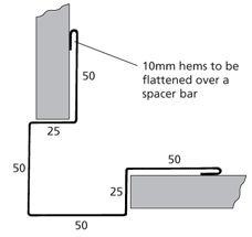
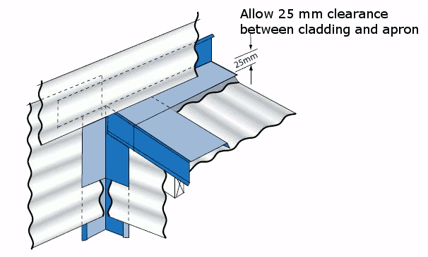
A simple and aesthetically pleasing detail to join abutting lengths of horizontal cladding is to provide a vertical break using a top hat or tee section flashing which the cladding sheets butt up to. As this is an express detail, the sheet ends are exposed and must be cut accurately, cleanly and at a consistent length to provide a tidy looking joint.
Designers should be aware of the likelihood of condensation when horizontal metal cladding is directly fixed to a lined and insulated wall The COP recomends sealing horizontal laps with lap tape or sealant. See Sealed Laps and Strip Sealants.
A ventilated cavity is the preferred option. See Condensation.
T Flashing
The COP recommends using the details in Jointer Flashing when sheets exceed 8 m to allow for ease of installation and thermal expansion. Foam filler blocks are recommended for exposed sites.
Butt flashings are not a recommended detail in areas of high design wind load. External flashings should be provided instead of, or in addition to, the butt joint flashings and they should be used in conjunction with stop-ends and filler blocks.
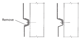
The fasteners in horizontal cladding should be clear of the hemmed soaker and should not penetrate the flashing.
- Log in to post comments

