
Ventilation Of Attic Spaces
It is said that money makes the world go around, but actually fashion is the driver, not only when talking women’s apparel but talking the building industry as well. A lot of house renovations are started just because it is ‘out of date’ or ’past its use by date’ or simply because it is ‘old-fashioned’. Fashion is good for architects and designers because they are in the fashion business too, and are always looking for something new and innovative which makes living a lot more exciting than sticking with the same old, same old.
Not all fashion is good design though and one such instance is the stiletto heel. Very popular with smart young ladies until they twisted their ankles or destroyed somebody’s timber or vinyl floor.
Not all building fashion is good design either and the fashion to try and make fibre cement or polystyrene walls look like concrete by bandaging up the joints with plaster was never a good idea. To use an organic material as the frame (timber) and an inorganic material (fibre cement sheeting) as the cladding and expecting them not to move was (and still is) bad design. That dumb fashion has cost individuals and the country heaps.
In New Zealand we went through a stage (BI- before insulation in 1977) when we all had leaky homes – except that they were not water leaky but ‘air-leaky’ (about 7 air changes an hour!) and after that date we (some of us) lost the plot. Because we now had wall and roof insulation it was assumed incorrectly that we had to gum up all the other holes to obtain the energy efficiency - the original aim. For the next three decades condensation loomed large as a problem, with metal roof cladding getting the blame for what was essentially a design problem, including mouldy ceilings and rotting timbers. Many were labelled as leaky homes when they were not leaking from the outside! This was bad design and that together with making buildings air tight and cladding buildings with fake concrete appears to the writer to be very like two stiletto designs.
We had turned our back on our original ventilation design standard which said:
NZS 3602: 1975: 24.2.3.1.
Roof cavities including cavities beneath flat roofs should be ventilated by such means as:
a) grilles in eaves;
b) louvre frames in gables;
c) a continuous gap in the roof soffit:
d) ventilating ridging: or
e) other suitable means
However the official (questionable) idea of not venting the attic space was carried on into E3/AS1 1.1.4.b which says: Insulated cavities shall be enclosed with no ventilation.
Breaking News!!
The E3/AS1 requirement of 1.1.4.b has now been deleted from E3/AS1.!!
After over 2 1/2 years, the lobbying by the MRM has paid off. Common sense has prevailed and because of this revision we can now legally vent our roof attic spaces again.
So are we back to 1975? - well no we’re not but fortunately the pendulum swing to energy efficiency at any cost has now gone too.
Prior to 1977 we had free air, since then no air, so now the swing of the pendulum needs to end up somewhere in the middle using controlled air ventilation.
We need to design into our buildings provision for some air movement - not too much - not too little. So now the designer has to work out what that is and how to fit it into his building design and the purpose of this article is to help designers do just that.
If you keep your Scope magazines, (as we hope you do) you could revisit Scope 29 where there was an article written on ventilation, and in two other adjacent Scopes 28 and 30 where articles can be found on insulation and condensation which will give the whole picture. Past issues can be downloaded from the MRM website. The Scope article on ventilation created much national discussion and the article contained a promise.
There is no doubt that New Zealand has a ventilation (or lack of) problem.
There is also no doubt that we have solutions to the problem.
Now is crunch time when we need to assist designers and show the details of just how passive ventilation can be designed into roof spaces. While the principle is the same for all roofs these details are more specific and intended for insulated ceiling spaces with metal roof cladding.
So how to design ventilation into the attic or skillion roof space- and the first question is how much ventilation?
The idea is that ventilating the attic air takes with the water vapour which is the real culprit.
Just how much air movement do we need to keep the attic space healthy? While every building will have a slightly different answer there already are some quantitative figures out there.
The NZMRM COP has suggested a maximum of ½ air change per hour based on the ceiling area of the building but this is dependent on many factors the two most important being the wind and the pitch of the roof. The pitch of the roof is important as flat roofs cannot take advantage of the stack (chimney) effect that a roof slope can provide. It is likely that even ¼ of an air change per hour would be adequate for an attic space but each ventilation design must take into account the type of roof, the design of the building and the site environment.
Because most of our ceilings are ‘vapour permeable’ there will always be some infiltration of moist air into the attic or skillion air space from below. Tenants are loathe to open windows for ventilation because they think they are wasting their energy dollars but are quite happy to buy a humidifier to try and solve their condensation problem (if you need one of these you have got a problem!). Not all clothes driers, showers and stoves are vented to the outside and you cannot stop your teen-age daughter spending hours in the shower. But assuming that good design has prevailed and the basics such as venting kitchen and bathroom fans to the exterior, air-tight attic hatches and no vented downlights have been followed then this should have prevented most water vapour from infiltrating the attic space.
We do not know the optimum amount or flow rate as this varies dependent on the number, habits and age of the occupants, but what we do know that a trickle of ventilation in attic spaces will solve most condensation problems.
The exposure of the site where there is ‘too much’ wind – very high and extra high - could provide too much air movement and in these cases the minimum venting is recommended which will minimise any decrease in the efficiency of the insulation due to what is termed ‘wind wash’. Loss of efficiency due to wind wash is not normally a problem in attic spaces providing the insulation is horizontal and the eave detail is correct but it can occur in skillion designs. All this air movement is above the insulation so while this could happen sometimes, the simplest and most efficient method of compensation is by overlaying the top of the insulation with a permeable underlay (an air barrier not a vapour barrier) or simply increasing the R value of the insulation. This can in fact turn out to be a win-win situation when using (say) 2/ R2.6 segments instead of an R5 segment a 4% increase in
R Value is obtained while saving about 11% in cost.
N.B. Although the actual minimum R value for roofs for Climate zones 1 & 2 is R 2.9 and R 3.3. for Climate Zone 3, this requirement is not simply satisfied by using the R value of the insulation used.
Unfortunately like a lot of similar situations in building there are no hard and fast rules as every building site is different and the designers judgement will determine the success or failure of the ventilation design.
The NZBC E3: 2004 has this to say:
E3.1 The objective of this provision is to-
(a) Safeguard people against illness, injury, or loss of amenity that could result from the accumulation of internal moisture;
E3.2 Buildings must be constructed to avoid the likelihood of
(b) Fungal growth or the accumulation of contaminants on linings and other building elements; and
(c) Damage to building elements being caused by the presence of moisture.
It stops short of saying how you can achieve this!!
While the NZBC emphasises IAQ (indoor air quality) there is no specific mention of attic spaces.
The COP 4.6 2003 has this to say:
To prevent moisture accumulation and to remove excess moisture in buildings with metal roof cladding, attic spaces should be ventilated using static, balanced ventilation systems with a total of 1m2 net free venting area per every 150m2 of ceiling area (0.6%)
While this agrees with the building codes of some countries others opt for ½ of that value @ 1/300. Ventilation designs within these parameters will in most instances provide air movement sufficient to avoid condensation problems. But it will not stop condensation forming on the underside of metal roofing
While UK figures vary considerably we are in the same ball-park.
BS 5250 has this to say:
Code of Practice for control of condensation in building.
It should be recognized that some energy will have to be expended on the removal of water vapour if condensation is to be controlled.
It is essential that adequate ventilation is provided to maintain the dew point temperature of the air below the inside surface temperature of the building envelope at all times.
BS 5250:2002, Amendment 1
UK ventilation requirements of free air space equivalent to a continuous opening in mm varies between 25mm and 5mm.
The differences between the two methods of calculation is the amount of ridge ventilation as in NZ we recommend inlets to have equal area outlet for maximum air movement. The requirement for less ventilation at the ridge, in the UK is because most of their roofs are clay and concrete tiles and are very permeable. The NZMRM COP attic space ventilation recommendations are made for impermeable metal roofs recognising that NZ has a greater problem of water vapour because of our high humidity and permeable ceilings. As water vapour is lighter than air we vent at highest point on the roof and the efficiency of a ridge vent depends on wind velocity and direction. Generally skillion and roofs < 10º require more free vent area as shown in the drawings.
The principle of passive ventilation is well known.
If there is a temperature or a pressure differential, then under the laws of equilibrium the temperatures and pressures will try to equalise. This equates to air movement but the common belief that hot air rises is actually not true! In fact it is the cold air that sinks under gravity. The fact remains air movement takes place and the hot air carries with it the moisture we are trying to get rid of (water vapour is 33% lighter than dry air).
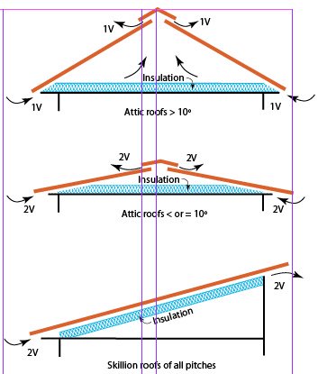 What is required is a designed space to vent it outside the building, however for the stack effect to work we need a balance of intake (lower) vents and outlet (higher) vents. If the design is a monopitch this requires equal air inlet and outlet areas whereas a duo-pitch gable would require soffit vents on both sides totalling the area of the ridge outlet vent. This system is termed passive ventilation because it does not use energy to extract the air or to condition it as most European air tight buildings require. We are looking for a healthy minimum of ventilation to balance energy efficiency, healthy homes and healthy occupants.
While a duo-pitch gable requires soffit vents on both sides it can have either a ridge vent or gable end vents. For skillion construction it is best to vent the barge on either side unless a polypropylene cavity batten is used on top of the purlin which is another option, while a mono-pitch can either have soffit/ridge vents or barge vents on both sides up the slope.
The important design parameter is to retain a ventilation path and where possible allow a 20mm air space either up and down or across the roof.
While the 20 mm dimension has been questioned this dimension has by default been assumed over time to be a safe gap because timber battens are nominally 20 millimetres. The NZMRM Code of Practice also advocates the use of underlayment which is only 6 mm high but covers the whole surface area of a roof providing the trickle ventilation which is most desirable.
What is not known is the minimum space required to provide trickle ventilation in different circumstances of wind or differential pressure, temperature and roof pitch for each specific site.
Worked examples as follows.
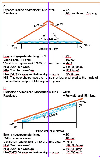
It can be seen from the two examples (above right) that the calculation of the amount of NFA required is not an exact science but requires the input of the designer to assess the site and construction. The broad parameters for design are recommended to be any NFA between 1/150 and 1/300 of the flat roof area of an insulated roof.
There are two unknown and variable forces at work, one is the stack effect which is determined by the pressure or temperature differential and the other is more variable and that is the wind. It is obvious that the steeper the roof the greater the air movement and that is why low pitched roofs require more ventilating area than steeper roofs.
The air movement required in roof spaces is not great but needs to be sufficient to keep the humidity to a level that the underlay under the metal roof cladding can work within its intended capacity. Supposed and perceived problems with synthetic underlays, have not been found to be with the product but with the overload of attic moisture due to lack of ventilation of moisture from below as this is many times more than the amount of roof cladding condensation from above.
The cost of this design fault has been many buildings that have had to be reroofed or redesigned because of condensation problems as often the insulation has been found to be hard up to the underlay without any provision for ventilation. The lack of ventilation has also led to a greater number of noise problems.
Continuous ridge vents were very popular in the 1960 – 80’s but cheaper designs leaked and they became unfashionable. Given good design and installation the ridge vent must be considered as an efficient and viable option. In the US, a type of Cupola ridge vent has become part of their style of architecture although they are seen in New Zealand also. This one is down the road from my home – note the long vertical inlet on the wall.
Gable end vents work well because they are placed at both ends of the ridge and provide cross ventilation and used with soffit vents they work independently of the wind direction. They also must be of a design that will not leak under extreme conditions and for this reason all the options offered have not copied overseas designs but are specifically intended for New Zealand conditions.
The photos ( taken in Auckland ) show that not all architects and designers have forgotten about attic space ventilation even though some may appear to inadequate! All built before the rot set in – about 1977!
These gable vents look promising except they are fake! If they had been for real they may have saved Sacramento apartment owners some of their rotten timbers! Many rotten buildings have been found to have no leaks – only condensation!
Many of the serious condensation problems that have arisen over the last couple of decades have occurred with skillion type roofs. This is not surprising as the air space volume left after the insulation has been stuffed into the gap is pretty well zilch. That is not to say that attic spaces don't have problems - they do but for different reasons.
There are four very different situations – attic, skillion, monopitch and duopitch and a different design type is required for each and new building and retrofits also need a slightly different approach.
All vents must be vermin proof and in marine environments must exclude salt aerosol which can be achieved by the use of a permeable membrane adhered to the back of vent grilles.
It is best to explore all the options for passive roof venting before opting for any alternative powered systems which are not energy efficient.
All of the following proprietary ventilation products are available through NZMRM metal roof cladding manufacturers.
SOFFIT VENTS
Soffit venting is common to all roof space venting systems.
NZ commonly uses 4.5mm fibre-cement for soffit linings with rebated timber fascia boards.
TEVS aluminium vent strips are made in two standard widths with 3mm slots either 50mm or 25mm long x 3.00m although other special sizes can be made to order.
The TEVS can be powder coated or have a permeable backing for marine environments. The TEVS fits into the standard groove of a fascia board while the two different sizes provide the designer with the options to balance ventilation for the site. Aluminium soffit vents can also be used on sloping barges and apex ridges.
The TEVS 50 has a NFA (net free area) of 17,500mm2 per lineal metre
TEVS 25 has a NFA of 9,500mm2 per lineal metre
The drawing ( above ) highlights a common major fault made by insulation installers who, by stuffing the insulation as far into the eave space as they can, effectively blocking off any air movement. A 20mm space is needed between the roof cladding or the purlin to provide ventilation between the soffit and the ridge or gable vents. While there are proprietary products made for this purpose, safety mesh stapled to the bottom or top chord is equally effective although this is not required if a cavity batten is used.
CAVITY BATTEN
A double polypropylene cavity batten (approximately 13,000 mm2 NFA) fixed above every purlin can be used to ventilate the attic space up the roof slope but the actual air movement is very much dependent other factors of the building design.
As an alternative to using soffit venting on barges, a single Cavity batten with insect mesh can be used behind a barge or apex flashing to provide approximately 5,000mm2 of NFA but again the actual flow is very dependent on the inlet area.
ALTERNATIVE VENTILATION SYSTEMS ‘WHIRLYBIRDS’
Extract from NZMRM Code of Practice 4.6.2.
Exhaust vents such as continuous or intermittent ridge vents, gable end vents and turbine vents should always be used in conjunction with intake vents.
Turbine vents rely on the wind to rotate the fan blades and when wind is present they draw air from the ventilated area at a greater rate than do passive vents when wind is present. The amount of air movement can be dampened but is normally uncontrolled as it is developed as a function of wind speed as well as turbine size and efficiency. They are not vulnerable to wind direction and their size and number can be calculated for a given air movement and wind speed.
One 300mm throat turbine vent will provide exhaust ventilation for a building of approximately 100m2.
VENTILATED RIDGING
Ventilated ridging or ridge vents work well in moderate wind conditions and exposure however they are not recommended without eave ventilation. (Drawing 5.8.A)
For flatter roofs additional baffles are recommended.
N.B. Underlay must not be carried over the ridge.
Solar is another exception to passive venting. Solar powered fans are designed only to operate when there is high humidity or temperature in the attic space.
This fan runs on Solar Power with a 12v Solar PV panel with a38v DC motor (with alternative mains power) with an adjustable thermostat and humidistat humidity control switch on at 75% RH & off at 65% RH. Energy usage is approximately 0.03kwh = $5 per year and the vent is adjustable to the orientation – it tilts and rotates.
One 600mm x 600mm x 270mm vent is suitable for 200m2 @ 18º pitch.
HEAT TRANSFER VENTILATING SYSTEMS
Any claims made by those promoting heat transfer ventilating systems to heat and ventilate your house are easily disproved if you do the science and the only advantage of those acceptable (those with fresh air inlets and a heat- exchanger) is that of trickle ventilation which you can get for free by passive ventilation.
Common sense and science have now prevailed and New Zealand can now re-join the rest of the world in venting their attic spaces. However the responsibility does fall on the designer as it his call as to what system is suitable for each project. All the information provided in this article is intended to assist designers to specify suitable products to comply with the recommended ventilation of attic and skillion roofs. If you have specific questions then most will be able to be answered by NZMRM members or their consultants.